|
电机参数的非线性变化导致电机在运行过程中存在转矩误差,而转矩误差过大容易导致转矩脉动、转速不稳,甚至影响整个控制系统的稳定运行[1]。因此如何完成电机转矩校准,实现对电机输出转矩的准确控制,是电动汽车永磁同步电机稳定性控制的关键。我们要介绍的就是通过电流环控制算法实现电机扭矩的精确控制。 1 电流环控制算法介绍[2]电流环控制常采用比例积分(PI)调节器,其中比例环节可以提高控制精度、减小系统偏差,积分环节可以消除系统稳态误差,但是传统的单 PI 参数电流调节器很难同时满足永磁同步电机全转速范围内电流环稳态性及快速性的控制要求,为实现电机额定转速以下电流的稳态无误差跟踪必然导致系统响应缓慢,为提高电机额定转速以上电流的动态响应必然产生超调。因此有人提出了一种模糊神经网络控制器,与传统 PI 控制器相比具有更好的静动态特性,但是神经网络算法十分复杂,模糊控制规则表需要进行大量的试验调试[3]。为了减少试验需求,有人提出了一种基于模糊控制的在线自适应控制算法,与传统的模糊控制及 PI 控制相比具有更强的带载能力和更强的适应性,但电机参数的在线精确辨识要求控制系统具有很高的数据采集速率及运算处理能力,大大增加了系统的设计成本,不利于推广应用[4]。后续有人提出了一种电流环解耦控制算法,通过对 dq 电流环的解耦提高电机的控制性能,但是该方法大多应用在低速电机控制,不符合电动汽车高转速运行的要求[5]。 2 两相旋转坐标系下的PMSM数学模型[6]数学模型假设条件: (1) 不考虑永磁体磁饱和影响,忽略磁滞损耗和涡流损耗;
(2) 忽略电机绕组漏感;
(3) 永磁材料电导率为零,永磁体内部的磁导率和空气相同;
(4) 不考虑电机运行过程中因摩擦产生的铜耗及铁耗;
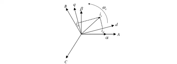
(5) 忽略温度、频率变化对电机参数的影响。      将定子磁链方程代入定子电压方程,可得:  当电机进入稳态运行时,上式中微分项为零,因此电机稳态运行方程为:  当电机工作在高速区时,电机定子压降可以忽略不计,定子电压方程可以简化为:  3 永磁同步电机矢量控制 3 永磁同步电机矢量控制矢量控制的基本思想是将定子电流矢量分解成励磁电流分量 <span class="MathJax_SVG" id="MathJax-Element-2-Frame" tabindex="0" data-mathml="id" role="presentation" style="display: inline-block; line-height: normal; font-size: 16px; word-spacing: normal; overflow-wrap: normal; white-space: nowrap; float: none; direction: ltr; max-width: none; max-height: none; min-width: 0px; min-height: 0px; border: 0px; position: relative;">id 和转矩电流分量 <span class="MathJax_SVG" id="MathJax-Element-1-Frame" tabindex="0" data-mathml="iq" role="presentation" style="display: inline-block; line-height: normal; font-size: 16px; word-spacing: normal; overflow-wrap: normal; white-space: nowrap; float: none; direction: ltr; max-width: none; max-height: none; min-width: 0px; min-height: 0px; border: 0px; position: relative;">iq ,且两分量相互垂直,彼此独立,如下图永磁同步电机电流矢量分解所示。矢量控制通过对励磁电流 <span class="MathJax_SVG" id="MathJax-Element-3-Frame" tabindex="0" data-mathml="id" role="presentation" style="display: inline-block; line-height: normal; font-size: 16px; word-spacing: normal; overflow-wrap: normal; white-space: nowrap; float: none; direction: ltr; max-width: none; max-height: none; min-width: 0px; min-height: 0px; border: 0px; position: relative;">id 和转矩电流 <span class="MathJax_SVG" id="MathJax-Element-4-Frame" tabindex="0" data-mathml="iq" role="presentation" style="display: inline-block; line-height: normal; font-size: 16px; word-spacing: normal; overflow-wrap: normal; white-space: nowrap; float: none; direction: ltr; max-width: none; max-height: none; min-width: 0px; min-height: 0px; border: 0px; position: relative;">iq 的独立控制来模拟直流电动机控制,从而将永磁同步电机控制简单化,获得良好的控制效果。 
永磁同步电机电流矢量分解永磁同步电机在进行矢量控制系统过程中,为了获得更好的控制效果常常对电压和电流的矢量轨迹进行优化,以便更好的控制这些量之间的相互关系,进而提高电机的调速范围。 在矢量控制系统中,PWM 信号需要经过Mosfet 等功率器件才能最终输出三相交流电压到永磁同步电机,而 Mosfet 等功率器件是一个具有额定电压额定电流容量限制的电子器件,因此加载在电机两端的电压及电流要求不能超过电机或功率器件的阈值,具体约束条件如下: <span class="MathJax_SVG" id="MathJax-Element-13-Frame" tabindex="0" data-mathml="us<ulim" role="presentation" style="display: inline-block; line-height: normal; font-size: 16px; word-spacing: normal; overflow-wrap: normal; white-space: nowrap; float: none; direction: ltr; max-width: none; max-height: none; min-width: 0px; min-height: 0px; border: 0px; position: relative;">us<ulim
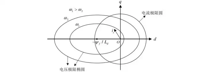
<span class="MathJax_SVG" id="MathJax-Element-5-Frame" tabindex="0" data-mathml="is<ilim" role="presentation" style="display: inline-block; line-height: normal; font-size: 16px; word-spacing: normal; overflow-wrap: normal; white-space: nowrap; float: none; direction: ltr; max-width: none; max-height: none; min-width: 0px; min-height: 0px; border: 0px; position: relative;">is<ilim 其中 <span class="MathJax_SVG" id="MathJax-Element-7-Frame" tabindex="0" data-mathml="us" role="presentation" style="display: inline-block; line-height: normal; font-size: 16px; word-spacing: normal; overflow-wrap: normal; white-space: nowrap; float: none; direction: ltr; max-width: none; max-height: none; min-width: 0px; min-height: 0px; border: 0px; position: relative;">us 为电机端电压; <span class="MathJax_SVG" id="MathJax-Element-10-Frame" tabindex="0" data-mathml="is" role="presentation" style="display: inline-block; line-height: normal; font-size: 16px; word-spacing: normal; overflow-wrap: normal; white-space: nowrap; float: none; direction: ltr; max-width: none; max-height: none; min-width: 0px; min-height: 0px; border: 0px; position: relative;">is 为电机端电流; <span class="MathJax_SVG" id="MathJax-Element-9-Frame" tabindex="0" data-mathml="ulim" role="presentation" style="display: inline-block; line-height: normal; font-size: 16px; word-spacing: normal; overflow-wrap: normal; white-space: nowrap; float: none; direction: ltr; max-width: none; max-height: none; min-width: 0px; min-height: 0px; border: 0px; position: relative;">ulim 、 <span class="MathJax_SVG" id="MathJax-Element-12-Frame" tabindex="0" data-mathml="ilim" role="presentation" style="display: inline-block; line-height: normal; font-size: 16px; word-spacing: normal; overflow-wrap: normal; white-space: nowrap; float: none; direction: ltr; max-width: none; max-height: none; min-width: 0px; min-height: 0px; border: 0px; position: relative;">ilim 为电机所能承受得最大电压、最大电流。  对于表贴式永磁同步电机,其 <span class="MathJax_SVG" id="MathJax-Element-8-Frame" tabindex="0" data-mathml="Ld=Lq" role="presentation" style="display: inline-block; line-height: normal; font-size: 16px; word-spacing: normal; overflow-wrap: normal; white-space: nowrap; float: none; direction: ltr; max-width: none; max-height: none; min-width: 0px; min-height: 0px; border: 0px; position: relative;">Ld=Lq ,此时方程变为一个圆方程,而对于嵌入式永磁同步电机来说, <span class="ztext-math" data-eeimg="1" data-tex="L_{d}<span class="MathJax_SVG" id="MathJax-Element-6-Frame" tabindex="0" data-mathml="Ld<Lq" role="presentation" style="display: inline-block; line-height: normal; font-size: 16px; word-spacing: normal; overflow-wrap: normal; white-space: nowrap; float: none; direction: ltr; max-width: none; max-height: none; min-width: 0px; min-height: 0px; border: 0px; position: relative;">Ld<Lq ,此时方程为椭圆方程,即为电压极限椭圆,圆心为 <span class="MathJax_SVG" id="MathJax-Element-11-Frame" tabindex="0" data-mathml="(−ψf/Ld,0)" role="presentation" style="display: inline-block; line-height: normal; font-size: 16px; word-spacing: normal; overflow-wrap: normal; white-space: nowrap; float: none; direction: ltr; max-width: none; max-height: none; min-width: 0px; min-height: 0px; border: 0px; position: relative;">(−ψf/Ld,0) ,当电机稳定运行时,极限椭圆的边界就是定子电压的最大值,且随着电机转速的增加,电压极限椭圆会缩小。 永磁同步电机稳态运行时,电流矢量之间的关系方程为: <span class="MathJax_SVG" id="MathJax-Element-14-Frame" tabindex="0" data-mathml="is=id2+iq2<ilim" role="presentation" style="display: inline-block; line-height: normal; font-size: 16px; word-spacing: normal; overflow-wrap: normal; white-space: nowrap; float: none; direction: ltr; max-width: none; max-height: none; min-width: 0px; min-height: 0px; border: 0px; position: relative;">is=id2+iq2<ilim 由方程可知,在 dq 坐标系下电机定子电流矢量si 的约束条件是一个以坐标原点为圆心的圆,称为电流极限圆。 
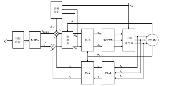
电压极限椭圆和电流极限圆矢量控制系统首先采集电机三相定子电流,接着根据磁动势等效原则进行坐标变换将三相定子电流转换为 dq 坐标系下的两相交轴电流 <span class="MathJax_SVG" id="MathJax-Element-17-Frame" tabindex="0" data-mathml="id" role="presentation" style="display: inline-block; line-height: normal; font-size: 16px; word-spacing: normal; overflow-wrap: normal; white-space: nowrap; float: none; direction: ltr; max-width: none; max-height: none; min-width: 0px; min-height: 0px; border: 0px; position: relative;">id 和 <span class="MathJax_SVG" id="MathJax-Element-19-Frame" tabindex="0" data-mathml="iq" role="presentation" style="display: inline-block; line-height: normal; font-size: 16px; word-spacing: normal; overflow-wrap: normal; white-space: nowrap; float: none; direction: ltr; max-width: none; max-height: none; min-width: 0px; min-height: 0px; border: 0px; position: relative;">iq ,然后求 <span class="MathJax_SVG" id="MathJax-Element-20-Frame" tabindex="0" data-mathml="id" role="presentation" style="display: inline-block; line-height: normal; font-size: 16px; word-spacing: normal; overflow-wrap: normal; white-space: nowrap; float: none; direction: ltr; max-width: none; max-height: none; min-width: 0px; min-height: 0px; border: 0px; position: relative;">id 和 <span class="MathJax_SVG" id="MathJax-Element-21-Frame" tabindex="0" data-mathml="iq" role="presentation" style="display: inline-block; line-height: normal; font-size: 16px; word-spacing: normal; overflow-wrap: normal; white-space: nowrap; float: none; direction: ltr; max-width: none; max-height: none; min-width: 0px; min-height: 0px; border: 0px; position: relative;">iq 的实际值与指令值之间的差值并利用电流调节器计算 dq 轴电压控制量 <span class="MathJax_SVG" id="MathJax-Element-16-Frame" tabindex="0" data-mathml="ud" role="presentation" style="display: inline-block; line-height: normal; font-size: 16px; word-spacing: normal; overflow-wrap: normal; white-space: nowrap; float: none; direction: ltr; max-width: none; max-height: none; min-width: 0px; min-height: 0px; border: 0px; position: relative;">ud 和 <span class="MathJax_SVG" id="MathJax-Element-18-Frame" tabindex="0" data-mathml="uq" role="presentation" style="display: inline-block; line-height: normal; font-size: 16px; word-spacing: normal; overflow-wrap: normal; white-space: nowrap; float: none; direction: ltr; max-width: none; max-height: none; min-width: 0px; min-height: 0px; border: 0px; position: relative;">uq,再经过 Park 变换输出 <span class="MathJax_SVG" id="MathJax-Element-24-Frame" tabindex="0" data-mathml="uα" role="presentation" style="display: inline-block; line-height: normal; font-size: 16px; word-spacing: normal; overflow-wrap: normal; white-space: nowrap; float: none; direction: ltr; max-width: none; max-height: none; min-width: 0px; min-height: 0px; border: 0px; position: relative;">uα 和 <span class="MathJax_SVG" id="MathJax-Element-15-Frame" tabindex="0" data-mathml="uβ" role="presentation" style="display: inline-block; line-height: normal; font-size: 16px; word-spacing: normal; overflow-wrap: normal; white-space: nowrap; float: none; direction: ltr; max-width: none; max-height: none; min-width: 0px; min-height: 0px; border: 0px; position: relative;">uβ 到 SVPWM 模块,SVPWM 模块根据 <span class="MathJax_SVG" id="MathJax-Element-22-Frame" tabindex="0" data-mathml="uα" role="presentation" style="display: inline-block; line-height: normal; font-size: 16px; word-spacing: normal; overflow-wrap: normal; white-space: nowrap; float: none; direction: ltr; max-width: none; max-height: none; min-width: 0px; min-height: 0px; border: 0px; position: relative;">uα、<span class="MathJax_SVG" id="MathJax-Element-23-Frame" tabindex="0" data-mathml="uβ" role="presentation" style="display: inline-block; line-height: normal; font-size: 16px; word-spacing: normal; overflow-wrap: normal; white-space: nowrap; float: none; direction: ltr; max-width: none; max-height: none; min-width: 0px; min-height: 0px; border: 0px; position: relative;">uβ及 Clark 反变换得到三相逆变器六路开关管的开通关断时间,最后输出 PWM 信号驱动 Mosfet 等功率器件产生三相交流电压输出到永磁同步电机。 
永磁同步电机矢量控制策略框图永磁同步电机全转速范围的稳定运行依赖于电流环的良好控制,当电机运行在额定转速以下时要求 dq 环电流能够稳态无误差跟踪,当电机运行在额定转速以上时要求 dq 环电流能够快速动态响应,电机工作不同的转速区域时对于电流环的不同要求大大增加了电流环调节器的设计难度。此外,永磁同步电机是一个高阶、时变的复杂被控对象,电机参数会随着负载电流及电机温升等电机运行状态的变化而变化,电机参数的非线性变化导致电机在运行过程中存在转矩误差,容易造成矢量控制系统转矩环振荡不利于整个系统的稳定性控制。而矢量控制主要是对永磁同步电机数学模型进行等效简化处理,缺少对电流环调节器的精确设计同时没有考虑电机参数非线性变化对于矢量控制系统转矩环的影响,为了提高永磁同步电机全转速范围控制的稳定性。 4 PMSM全转速范围控制根据永磁同步电机全转速范围的工作特性,可以将其控制分为恒转矩启动控制区和恒功率弱磁加速区: 
电动汽车驱动电机理想驱动曲线根据电动汽车的应用场景,当电动汽车工作在低速时需要电机能够输出较大的转矩以满足电动汽车频繁启动、快速起步及爬坡等需求,由于逆变器功率等级的限制永磁同步电机在输出大转矩时所需要的定子电流应当尽可能小。此外随着电动汽车转速的逐渐升高,电机的反向电动势越来越大,当加载在电机上的端电压达到电池组及逆变器所能提供的最大值时,想要继续提高电机的运行转速进而扩大系统的调速范围以满足电动汽车超车及加速需求,就需要对电机进行弱磁。电动汽车全转速范围的控制目标可以概括为在电机全转速范围内都能输出峰值转矩、峰值功率,同时能够达到峰值转速。 4.1 恒转矩区控制方法永磁同步电机工作在额定转速以下恒转矩区时,需要很大的启动转矩及很快的转矩响应,永磁同步电机恒转矩区主要有两种控制方法: <span class="MathJax_SVG" id="MathJax-Element-25-Frame" tabindex="0" data-mathml="id=0" role="presentation" style="display: inline-block; line-height: normal; font-size: 16px; word-spacing: normal; overflow-wrap: normal; white-space: nowrap; float: none; direction: ltr; max-width: none; max-height: none; min-width: 0px; min-height: 0px; border: 0px; position: relative;">id=0 和最大转矩电流比(Maximum Torque per Ampere,MTPA)控制。贴式永磁同步电机永磁体内部气隙均匀分布,磁导率接近空气,因此 <span class="MathJax_SVG" id="MathJax-Element-26-Frame" tabindex="0" data-mathml="Ld=Lq" role="presentation" style="display: inline-block; line-height: normal; font-size: 16px; word-spacing: normal; overflow-wrap: normal; white-space: nowrap; float: none; direction: ltr; max-width: none; max-height: none; min-width: 0px; min-height: 0px; border: 0px; position: relative;">Ld=Lq,磁阻转矩为零,由电磁转矩方程可知电机的转矩输出只与交轴电流相关。而对于嵌入式永磁同步电机来说,其交直轴电感不等,内部存在磁阻转矩,MTPA 控制与 <span class="MathJax_SVG" id="MathJax-Element-27-Frame" tabindex="0" data-mathml="id=0" role="presentation" style="display: inline-block; line-height: normal; font-size: 16px; word-spacing: normal; overflow-wrap: normal; white-space: nowrap; float: none; direction: ltr; max-width: none; max-height: none; min-width: 0px; min-height: 0px; border: 0px; position: relative;">id=0 控制相比能够充分利用磁阻转矩以提高电机单位定子电流的转矩输出能力,减小电流产生的损耗,进而提高电机的运行效率。 
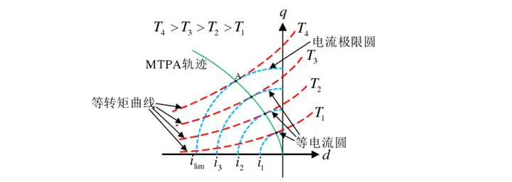
电磁转矩方程电磁转矩方程可以得到一系列等转矩曲线,而每条等转矩曲线与 dq 坐标系下的一系列等电流圆都存在一个切点(交直轴电感的情况),当电机工作在这些切点时单位定子电流的电磁转矩输出能力最大,将这些点连起来就可以得到最大转矩电流比(MTPA)曲线,如下图所示: 
转子旋转坐标系下的MTPA轨迹根据永磁同步电机转子旋转坐标系下的电磁转矩方程及电流极限圆,可得:  构造辅助函数:  式中, <span class="MathJax_SVG" id="MathJax-Element-30-Frame" tabindex="0" data-mathml="λ" role="presentation" style="display: inline-block; line-height: normal; font-size: 16px; word-spacing: normal; overflow-wrap: normal; white-space: nowrap; float: none; direction: ltr; max-width: none; max-height: none; min-width: 0px; min-height: 0px; border: 0px; position: relative;">λ 为拉格朗日乘数。分别对 <span class="MathJax_SVG" id="MathJax-Element-29-Frame" tabindex="0" data-mathml="id" role="presentation" style="display: inline-block; line-height: normal; font-size: 16px; word-spacing: normal; overflow-wrap: normal; white-space: nowrap; float: none; direction: ltr; max-width: none; max-height: none; min-width: 0px; min-height: 0px; border: 0px; position: relative;">id 和 <span class="MathJax_SVG" id="MathJax-Element-28-Frame" tabindex="0" data-mathml="iq" role="presentation" style="display: inline-block; line-height: normal; font-size: 16px; word-spacing: normal; overflow-wrap: normal; white-space: nowrap; float: none; direction: ltr; max-width: none; max-height: none; min-width: 0px; min-height: 0px; border: 0px; position: relative;">iq 求偏导,并令偏导数等于零,得:  该式即为 dq 坐标系下的 MTPA 的核心方程。MTPA 轨迹与电流极限圆的交点为 A,该点为电机所能输出的最大转矩点,同时也是电机的转速转折点(基速点),永磁同步电机工作在 MTPA 曲线时,定子电流幅值最小,电机运行过程中的损耗最小,系统效率最高。 4.2 弱磁区控制方法随着电机转速的不断增高,电机的反向电动势越来越大,当加载在电机上的端电压达到电动汽车电池组经过逆变器所能提供的电压最大值时,电机速度达到最大值即额定转速,想要继续提高电机的运行转速扩宽电机的调速范围,就需要对电机进行弱磁。 对于嵌入式永磁同步电机来说,永磁体转子产生的磁通大小不变,想要改变电机磁通只有通过降低励磁电流,即负向增加直轴电流分量 <span class="MathJax_SVG" id="MathJax-Element-31-Frame" tabindex="0" data-mathml="id" role="presentation" style="display: inline-block; line-height: normal; font-size: 16px; word-spacing: normal; overflow-wrap: normal; white-space: nowrap; float: none; direction: ltr; max-width: none; max-height: none; min-width: 0px; min-height: 0px; border: 0px; position: relative;">id 以削弱电机磁场实现弱磁控制。根据电机转速的大小,定子电流矢量可以分为两个区域:恒转矩区和弱磁区,同时弱磁区又可以分为弱磁一区和弱磁二区。 
弱磁控制电流轨迹图在恒转矩区,定子电流矢量沿 MTPA 曲线移动,即图中 OA 曲线段。A 点为MTPA 曲线与电流极限圆的交点,定子电流达到逆变器所能承受的电流最大值,电动汽车电池组经过逆变器所能输出的交流侧电压达到最大,对应转速为电机额定转速 <span class="MathJax_SVG" id="MathJax-Element-33-Frame" tabindex="0" data-mathml="ω1" role="presentation" style="display: inline-block; line-height: normal; font-size: 16px; word-spacing: normal; overflow-wrap: normal; white-space: nowrap; float: none; direction: ltr; max-width: none; max-height: none; min-width: 0px; min-height: 0px; border: 0px; position: relative;">ω1 , <span class="MathJax_SVG" id="MathJax-Element-32-Frame" tabindex="0" data-mathml="ω1" role="presentation" style="display: inline-block; line-height: normal; font-size: 16px; word-spacing: normal; overflow-wrap: normal; white-space: nowrap; float: none; direction: ltr; max-width: none; max-height: none; min-width: 0px; min-height: 0px; border: 0px; position: relative;">ω1 为电机第一转折速度。 在弱磁一区,逆变器交流侧输出电压达到其最大值后电流内环调节器饱和,要继续升高电机转速,需要增加直轴的励磁电流分量,使得定子电流能够沿着电流极限圆 AB 段运行。当电机运行到 B 点时,MTPA 曲线与电压极限椭圆再无交点,电机的工作点被限制在电流和电压极限圆内,对应转速为 <span class="MathJax_SVG" id="MathJax-Element-37-Frame" tabindex="0" data-mathml="ω2" role="presentation" style="display: inline-block; line-height: normal; font-size: 16px; word-spacing: normal; overflow-wrap: normal; white-space: nowrap; float: none; direction: ltr; max-width: none; max-height: none; min-width: 0px; min-height: 0px; border: 0px; position: relative;">ω2(\omega_{1}"><span class="MathJax_SVG" id="MathJax-Element-36-Frame" tabindex="0" data-mathml="ω2>ω1" role="presentation" style="display: inline-block; line-height: normal; font-size: 16px; word-spacing: normal; overflow-wrap: normal; white-space: nowrap; float: none; direction: ltr; max-width: none; max-height: none; min-width: 0px; min-height: 0px; border: 0px; position: relative;">ω2>ω1),<span class="MathJax_SVG" id="MathJax-Element-35-Frame" tabindex="0" data-mathml="ω2" role="presentation" style="display: inline-block; line-height: normal; font-size: 16px; word-spacing: normal; overflow-wrap: normal; white-space: nowrap; float: none; direction: ltr; max-width: none; max-height: none; min-width: 0px; min-height: 0px; border: 0px; position: relative;">ω2 为电机第二转折速度。 在弱磁二区,当转速大于 <span class="MathJax_SVG" id="MathJax-Element-34-Frame" tabindex="0" data-mathml="ω2" role="presentation" style="display: inline-block; line-height: normal; font-size: 16px; word-spacing: normal; overflow-wrap: normal; white-space: nowrap; float: none; direction: ltr; max-width: none; max-height: none; min-width: 0px; min-height: 0px; border: 0px; position: relative;">ω2 后,电机不再具备带较大负载的能力,此时需要控制定子电流矢量使其沿着最大转矩电压比(Maximum Torque per Voltage,MTPV)曲线运行,当负载转矩相同时,MTPV 曲线上的点消耗的电压最小,转速范围提升的空间也较宽,定子电流矢量将沿着图中 B 点向 C 点移动上升至最大转速。 此外,由于电机设计不同,当特征点 C 不在电流极限圆即 <span class="MathJax_SVG" id="MathJax-Element-38-Frame" tabindex="0" data-mathml="ψf/Ld≥ilim" role="presentation" style="display: inline-block; line-height: normal; font-size: 16px; word-spacing: normal; overflow-wrap: normal; white-space: nowrap; float: none; direction: ltr; max-width: none; max-height: none; min-width: 0px; min-height: 0px; border: 0px; position: relative;">ψf/Ld≥ilim 时,将不存在 BC 段曲线,定子电流矢量将沿弱磁 1 区曲线移动至电机最大转速。 5 PMSM全转速范围策略永磁同步电机全转速范围转矩控制策略首先利用转矩校准算法消除电机参数非线性变化产生的转矩误差,增强矢量控制系统转矩闭环的稳定性,然后通过电流环的闭环控制实现转矩的闭环控制。其中电流环的闭环控制采用变增益电流环控制算法实现电机任意转速区域内 dq 环反馈电流 <span class="MathJax_SVG" id="MathJax-Element-41-Frame" tabindex="0" data-mathml="id" role="presentation" style="display: inline-block; line-height: normal; font-size: 16px; word-spacing: normal; overflow-wrap: normal; white-space: nowrap; float: none; direction: ltr; max-width: none; max-height: none; min-width: 0px; min-height: 0px; border: 0px; position: relative;">id 和 <span class="MathJax_SVG" id="MathJax-Element-40-Frame" tabindex="0" data-mathml="iq" role="presentation" style="display: inline-block; line-height: normal; font-size: 16px; word-spacing: normal; overflow-wrap: normal; white-space: nowrap; float: none; direction: ltr; max-width: none; max-height: none; min-width: 0px; min-height: 0px; border: 0px; position: relative;">iq对指令电流 <span class="MathJax_SVG" id="MathJax-Element-42-Frame" tabindex="0" data-mathml="id∗" role="presentation" style="display: inline-block; line-height: normal; font-size: 16px; word-spacing: normal; overflow-wrap: normal; white-space: nowrap; float: none; direction: ltr; max-width: none; max-height: none; min-width: 0px; min-height: 0px; border: 0px; position: relative;">id∗ 和 <span class="MathJax_SVG" id="MathJax-Element-39-Frame" tabindex="0" data-mathml="iq∗" role="presentation" style="display: inline-block; line-height: normal; font-size: 16px; word-spacing: normal; overflow-wrap: normal; white-space: nowrap; float: none; direction: ltr; max-width: none; max-height: none; min-width: 0px; min-height: 0px; border: 0px; position: relative;">iq∗ 的稳态无误差动态无超调跟踪,提高电流环的动态特性和鲁棒性,最终实现永磁同步电机全转速范围的稳定高性能运行。 
PMSM全转速范围策略6 基于前馈补偿得电流环解耦控制传统的电流控制方案采用两个PI调节器对dq轴电流进行独立控制。采用电压型逆变器时,其转子旋转坐标系下电压分量表达式如下所示[7]: 
传统PI电流调节器传统PI电流调节器结构简单、易于实现,但忽略了dq轴交叉耦合的影响。交叉耦合项的影响与速度相关,在速度调节过程中或高速段耦合作用显著,仅依靠PI调节器进行电流调节,不能满足性能要求。 基于PMSM数学方程中电压方程与磁链方程,可以得到以下方程。传统的PI调节器的输出电压一部分抵消反电动势,一部分用于控制交直轴电流,增加了调节时间,降低了调节精度和系统动态性能。  为了解决这一问题,我们可以加入前馈补偿,以提高系统的动态性能:   由此可以得到以反馈电流为输入的电压前馈补偿型电流调节器框图: 
电压前馈补偿型电流调节器
|