本帖最后由 hanter 于 2023-1-5 09:11 编辑
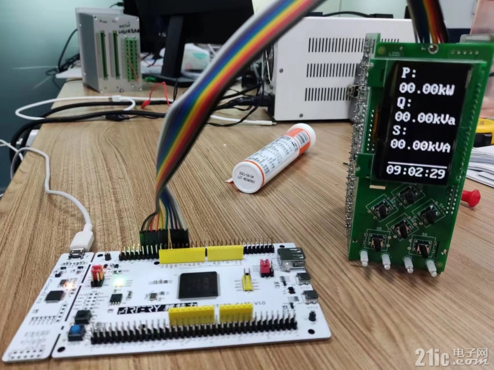
分享一个我在项目中使用到的oled显示驱动,拓扑微CUG-2864ASWPG14 128*64的oled,使用IO口模拟实现并口驱动。
- #define E_H() (gpio_bits_set(LCD_RD_GPIO_Port,LCD_RD_Pin)) //(LCD_RD_GPIO_Port->BSRRL = LCD_RD_Pin )//RD
- #define E_L() (gpio_bits_reset(LCD_RD_GPIO_Port,LCD_RD_Pin)) //(LCD_RD_GPIO_Port->BSRRH = LCD_RD_Pin )
- #define A0_H() (gpio_bits_set(LCD_RS_GPIO_Port,LCD_RS_Pin)) //(LCD_RS_GPIO_Port->BSRRL = LCD_RS_Pin ) //H数据/L指令 RS
- #define A0_L() (gpio_bits_reset(LCD_RS_GPIO_Port,LCD_RS_Pin)) //(LCD_RS_GPIO_Port->BSRRH = LCD_RS_Pin )
- #define RW_H() (gpio_bits_set(LCD_WR_GPIO_Port,LCD_WR_Pin)) //(LCD_WR_GPIO_Port->BSRRL = LCD_WR_Pin ) //RW
- #define RW_L() (gpio_bits_reset(LCD_WR_GPIO_Port,LCD_WR_Pin)) //(LCD_WR_GPIO_Port->BSRRH = LCD_WR_Pin )
- #define CS_H() (gpio_bits_set(LCD_CSE1_GPIO_Port,LCD_CSE1_Pin)) //(LCD_CSE1_GPIO_Port->BSRRL = LCD_CSE1_Pin ) //CSE1
- #define CS_L() (gpio_bits_reset(LCD_CSE1_GPIO_Port,LCD_CSE1_Pin)) //(LCD_CSE1_GPIO_Port->BSRRH = LCD_CSE1_Pin )
- #define RST_H() (gpio_bits_set(LCD_RST_GPIO_Port,LCD_RST_Pin)) //(LCD_RST_GPIO_Port->BSRRL = LCD_RST_Pin ) //RST
- #define RST_L() (gpio_bits_reset(LCD_RST_GPIO_Port,LCD_RST_Pin)) //(LCD_RST_GPIO_Port->BSRRH = LCD_RST_Pin )
- #define BLA_H() (gpio_bits_set(LCD_LED_GPIO_Port,LCD_LED_Pin)) //(LCD_LED_GPIO_Port->BSRRL = LCD_LED_Pin ) //LCDLED
- #define BLA_L() (gpio_bits_reset(LCD_LED_GPIO_Port,LCD_LED_Pin)) //(LCD_LED_GPIO_Port->BSRRH = LCD_LED_Pin )
- #define ADC_L() //(GPIOA->BRR = GPIO_Pin_7 )
- void DBOUT(BYTE data)
- {
- if (data & 0x80)
- (gpio_bits_set(LCD_DB7_GPIO_Port, LCD_DB7_Pin)); //LCD_DB7_GPIO_Port->BSRRL = LCD_DB7_Pin;
- else
- (gpio_bits_reset(LCD_DB7_GPIO_Port, LCD_DB7_Pin)); //LCD_DB7_GPIO_Port->BSRRH = LCD_DB7_Pin;
- if (data & 0x40)
- (gpio_bits_set(LCD_DB6_GPIO_Port, LCD_DB6_Pin)); //LCD_DB6_GPIO_Port->BSRRL = LCD_DB6_Pin;
- else
- (gpio_bits_reset(LCD_DB6_GPIO_Port, LCD_DB6_Pin)); //LCD_DB6_GPIO_Port->BSRRH = LCD_DB6_Pin;
- if (data & 0x20)
- (gpio_bits_set(LCD_DB5_GPIO_Port, LCD_DB5_Pin)); //LCD_DB5_GPIO_Port->BSRRL = LCD_DB5_Pin;
- else
- (gpio_bits_reset(LCD_DB5_GPIO_Port, LCD_DB5_Pin)); //LCD_DB5_GPIO_Port->BSRRH = LCD_DB5_Pin;
- if (data & 0x10)
- (gpio_bits_set(LCD_DB4_GPIO_Port, LCD_DB4_Pin)); //LCD_DB4_GPIO_Port->BSRRL = LCD_DB4_Pin;
- else
- (gpio_bits_reset(LCD_DB4_GPIO_Port, LCD_DB4_Pin)); //LCD_DB4_GPIO_Port->BSRRH = LCD_DB4_Pin;
- if (data & 0x08)
- (gpio_bits_set(LCD_DB3_GPIO_Port, LCD_DB3_Pin)); //LCD_DB3_GPIO_Port->BSRRL = LCD_DB3_Pin;
- else
- (gpio_bits_reset(LCD_DB3_GPIO_Port, LCD_DB3_Pin)); //LCD_DB3_GPIO_Port->BSRRH = LCD_DB3_Pin;
- if (data & 0x04)
- (gpio_bits_set(LCD_DB2_GPIO_Port, LCD_DB2_Pin)); //LCD_DB2_GPIO_Port->BSRRL = LCD_DB2_Pin;
- else
- (gpio_bits_reset(LCD_DB2_GPIO_Port, LCD_DB2_Pin)); //LCD_DB2_GPIO_Port->BSRRH = LCD_DB2_Pin;
- if (data & 0x02)
- (gpio_bits_set(LCD_DB1_GPIO_Port, LCD_DB1_Pin)); //LCD_DB1_GPIO_Port->BSRRL = LCD_DB1_Pin;
- else
- (gpio_bits_reset(LCD_DB1_GPIO_Port, LCD_DB1_Pin)); //LCD_DB1_GPIO_Port->BSRRH = LCD_DB1_Pin;
- if (data & 0x01)
- (gpio_bits_set(LCD_DB0_GPIO_Port, LCD_DB0_Pin)); //LCD_DB0_GPIO_Port->BSRRL = LCD_DB0_Pin;
- else
- (gpio_bits_reset(LCD_DB0_GPIO_Port, LCD_DB0_Pin)); //LCD_DB0_GPIO_Port->BSRRH = LCD_DB0_Pin;
- }
- static void delay(int16 n)
- {
- int8 i;
- for(; n>0; n--)
- {
- for(i=3; i>0; i--);
- }
- }
- static void WriteData(unsigned char DATA)
- {
- //CheckBusy();
- CS_L();
- E_H();
- A0_H();
- DBOUT(DATA);
- RW_L();
- delay(1);
- RW_H();
- CS_H();
- }
- static void WriteCommand(unsigned char command)
- {
- //CheckBusy();
- CS_L();
- E_H();
- A0_L();
- DBOUT(command);
- RW_L();
- delay(1);
- RW_H();
- CS_H();
- }
- void Lcd_Init_RST(void)
- {
- //WriteCommand(0xae); /* set display off */
- WriteCommand(0x00); /* set lower column start address */
- WriteCommand(0x10); /* set higher column start address */
- WriteCommand(0xD5); /* set display clock divide/oscillator frequency */
- WriteCommand(0xA0);
- WriteCommand(0xA8); /* set multiplex ratio */
- WriteCommand(0x3F);
- // WriteCommand(0xD3); /* set display offset */
- // WriteCommand(0x00);
- WriteCommand(0x40); /* set display start line */
- WriteCommand(0x00);
- WriteCommand(0x20); /* set Memory Addressing Mode */
- WriteCommand(0x02);
- WriteCommand(0xa0); /* set segment remap */
- WriteCommand(0xC8); /* Set COM Output Scan Direction */
- WriteCommand(0xDA); /* Set COM Pins Hardware Configuration */
- WriteCommand(0x12);
- WriteCommand(0xc0); /* set com scan direction */
- WriteCommand(0xd3); /* set display offset */
- WriteCommand(0x40);
- WriteCommand(0x81); /* set contrast control */
- WriteCommand(0xBF);
- WriteCommand(0xD9); /* set Pre-charge Period */
- WriteCommand(0x25);
- WriteCommand(0xA4); /* entire display on */
- WriteCommand(0xA6); /* set normal/inverse display */
- WriteCommand(0xaf); /* set display on */
- }


|