本帖最后由 hbzjt2011 于 2020-12-7 20:15 编辑
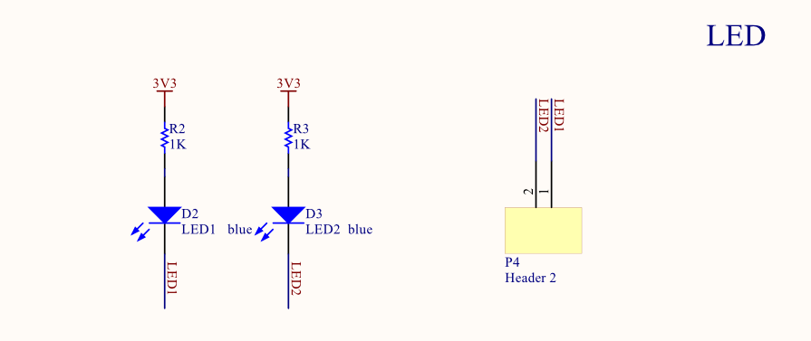
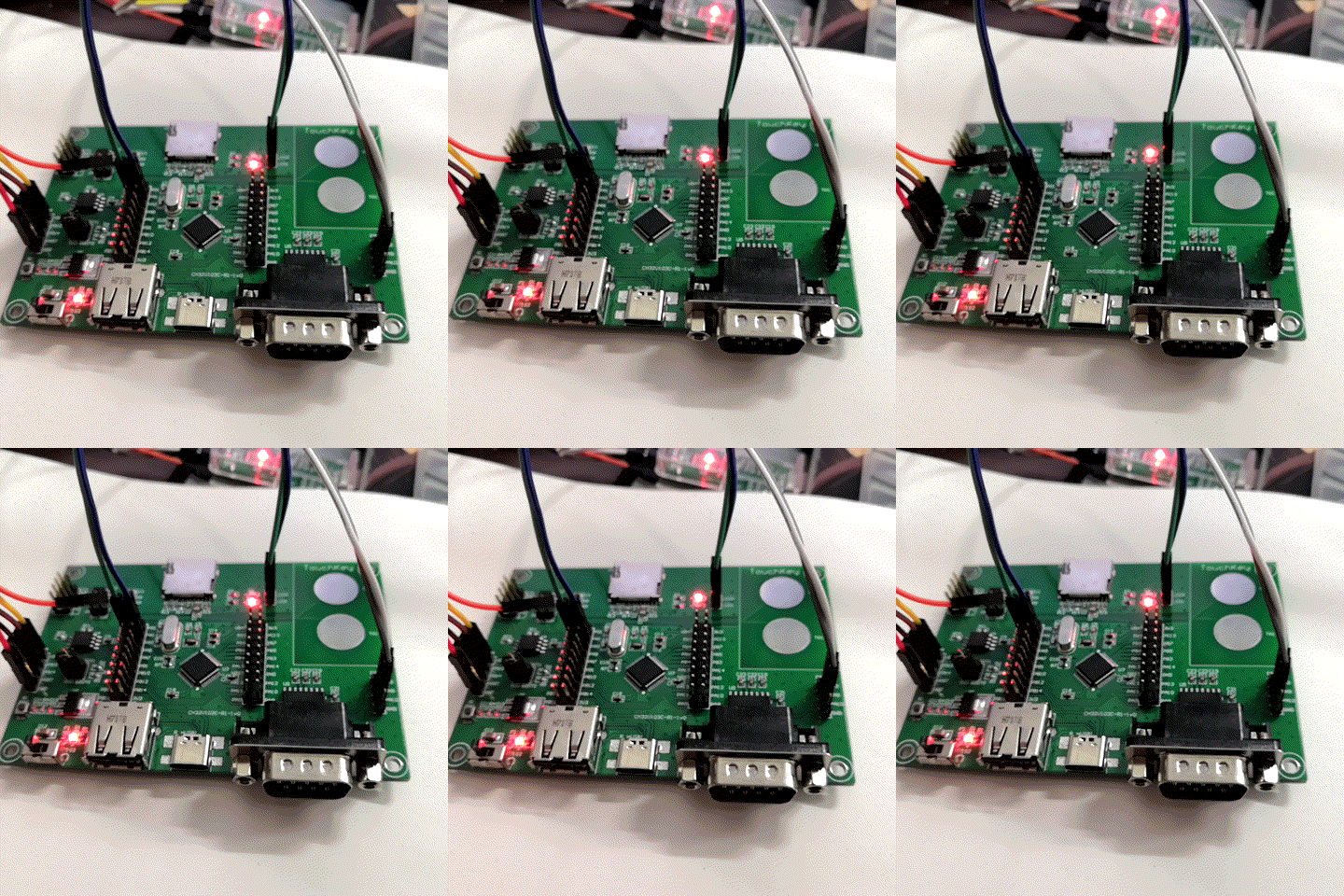
熟悉了CH32V103处理器在MounRiver Studio下的开发流程以后,开始利用评估板上的外设和硬件资源进行程序的编写。首先评估板上自带两个LED灯,可以用来做流水灯和PWM呼吸灯。

在已有的程序结构中添加Hardware->LED文件夹,同时将LED.c源文件和led.h头文件增加到项目中。同时需要将头文件路径添加到头文件目录中,在MounRiver Studio软件中的构建设置中增加LED目录。


然后分别在led.c中编写LED端口初始化程序,包括控制端口时钟使能以及端口参数设置;在头文件中增加函数原型声明和相关的宏定义。
led.c文件:
- #include "led.h"
- void LED_Init(void)
- {
- GPIO_InitTypeDef GPIO_InitStructure; //定义一个GPIO_InitTypeDef类型的结构体
- RCC_APB2PeriphClockCmd(RCC_APB2Periph_GPIOA, ENABLE); //使能与LED相关的GPIO端口时钟
- GPIO_InitStructure.GPIO_Pin = LED1_PIN | LED2_PIN; //配置GPIO引脚
- GPIO_InitStructure.GPIO_Mode = GPIO_Mode_Out_PP; //设置GPIO模式为推挽输出
- GPIO_InitStructure.GPIO_Speed = GPIO_Speed_50MHz; //设置GPIO口输出速度
- GPIO_Init(LED_PORT, &GPIO_InitStructure); //调用库函数,初始化GPIOA
- GPIO_SetBits(LED_PORT,LED1_PIN | LED2_PIN); //设置引脚输出高电平
- }
- #ifndef __LED_H
- #define __LED_H
- #include "ch32v10x_conf.h"
- #define LED_PORT GPIOA
- #define LED1_PIN GPIO_Pin_0
- #define LED2_PIN GPIO_Pin_1
- #define LED1_ON (GPIO_WriteBit(LED_PORT, LED1_PIN, Bit_RESET))
- #define LED1_OFF (GPIO_WriteBit(LED_PORT, LED1_PIN, Bit_SET))
- #define LED2_ON (GPIO_WriteBit(LED_PORT, LED2_PIN, Bit_RESET))
- #define LED2_OFF (GPIO_WriteBit(LED_PORT, LED2_PIN, Bit_SET))
- #define LED1_Toggle (GPIO_WriteBit(LED_PORT, LED1_PIN, (1-GPIO_ReadOutputDataBit(LED_PORT, LED1_PIN))))
- #define LED2_Toggle (GPIO_WriteBit(LED_PORT, LED2_PIN, (1-GPIO_ReadOutputDataBit(LED_PORT, LED2_PIN))))
- void LED_Init(void); //初始化
- #endif
- int main(void)
- {
- NVIC_PriorityGroupConfig(NVIC_PriorityGroup_2);
- Delay_Init();
- USART_Printf_Init(115200);
- printf("SystemClk:%d\r\n",SystemCoreClock);
- printf("This is printf example\r\n");
- LED_Init();
- LED1_ON;
- LED2_OFF;
- while(1)
- {
- LED1_Toggle;
- LED2_Toggle;
- Delay_Ms(500);
- }
- }

| 