- /******************************************************************************
- * Include files
- ******************************************************************************/
- #include "main.h"
- #include "cw32f030_systick.h"
- #include "cw32f030_rcc.h"
- #include "cw32f030_gpio.h"
- #include "cw32f030_adc.h"
- /******************************************************************************
- * Local pre-processor symbols/macros ('#define')
- ******************************************************************************/
- //UARTx
- #define DEBUG_USARTx CW_UART1
- #define DEBUG_USART_CLK RCC_APB2_PERIPH_UART1
- #define DEBUG_USART_APBClkENx RCC_APBPeriphClk_Enable2
- #define DEBUG_USART_BaudRate 9600
- #define DEBUG_USART_UclkFreq 8000000
- //UARTx GPIO
- #define DEBUG_USART_GPIO_CLK RCC_AHB_PERIPH_GPIOA
- #define DEBUG_USART_TX_GPIO_PORT CW_GPIOA
- #define DEBUG_USART_TX_GPIO_PIN GPIO_PIN_8
- #define DEBUG_USART_RX_GPIO_PORT CW_GPIOA
- #define DEBUG_USART_RX_GPIO_PIN GPIO_PIN_9
- //GPIO AF
- #define DEBUG_USART_AFTX PA08_AFx_UART1TXD()
- #define DEBUG_USART_AFRX PA09_AFx_UART1RXD()
- //中断
- #define DEBUG_USART_IRQ UART1_IRQn
- #define max_adc_cnt 50
- // 按键接口 PA5和PA6
- #define KEY_GPIO_PINS GPIO_PIN_5 | GPIO_PIN_6
- /******************************************************************************
- * Global variable definitions (declared in header file with 'extern')
- ******************************************************************************/
- uint16_t valueAdc;
- uint32_t valueAdcAcc;
- volatile uint8_t gFlagIrq;
- uint16_t gCntEoc = 0; // ADC转换次数
- uint16_t gCntAcc = 0; // ADC转换数据累加次数
- uint8_t cntSample;
- volatile uint8_t gKeyFlagIrq=0;
- uint16_t valueAllAdc[max_adc_cnt]; // 50组数据
- uint8_t pos=0; // 保存数据的数组下表
- float maxval=0; // 未充电时最大值
- float stdval=0; // 未充电时最大值作为比较标准
- uint8_t chgflag=0; // 充电标志
- /******************************************************************************
- * Local type definitions ('typedef')
- ******************************************************************************/
- /******************************************************************************
- * Local function prototypes ('static')
- ******************************************************************************/
- void RCC_Configuration(void);
- void GPIO_Configuration(void);
- void UART_Configuration(void);
- void NVIC_Configuration(void);
- void USART_SendString(UART_TypeDef* USARTx, char *String);
- void adc_Init(void);
- void LED_Init(void);
- void init(void);
- /******************************************************************************
- * Local variable definitions ('static') *
- ******************************************************************************/
- /******************************************************************************
- * Local pre-processor symbols/macros ('#define')
- ******************************************************************************/
- /*****************************************************************************
- * Function implementation - global ('extern') and local ('static')
- ******************************************************************************/
- /**
- * [url=home.php?mod=space&uid=247401]@brief[/url] 循环延时
- *
- * @param nCount
- */
- void Delay(__IO uint16_t nCount) {
- /* Decrement nCount value */
- while (nCount != 0) {
- nCount--;
- }
- }
- /**
- * [url=home.php?mod=space&uid=247401]@brief[/url] 配置RCC
- *
- */
- void RCC_Configuration(void) {
- //SYSCLK = HSI = 8MHz = HCLK = PCLK
- RCC_HSI_Enable(RCC_HSIOSC_DIV6);
- //外设时钟使能
- RCC_AHBPeriphClk_Enable(DEBUG_USART_GPIO_CLK, ENABLE);
- DEBUG_USART_APBClkENx(DEBUG_USART_CLK, ENABLE);
- }
- /**
- * @brief 配置GPIO
- *
- */
- void GPIO_Configuration(void) {
- GPIO_InitTypeDef GPIO_InitStructure;
- //UART TX RX 复用
- DEBUG_USART_AFTX;
- DEBUG_USART_AFRX;
- GPIO_InitStructure.Pins = DEBUG_USART_TX_GPIO_PIN;
- GPIO_InitStructure.Mode = GPIO_MODE_OUTPUT_PP;
- GPIO_InitStructure.Speed = GPIO_SPEED_HIGH;
- GPIO_Init(DEBUG_USART_TX_GPIO_PORT, &GPIO_InitStructure);
- GPIO_InitStructure.Pins = DEBUG_USART_RX_GPIO_PIN;
- GPIO_InitStructure.Mode = GPIO_MODE_INPUT_PULLUP;
- GPIO_Init(DEBUG_USART_RX_GPIO_PORT, &GPIO_InitStructure);
-
-
- __RCC_GPIOA_CLK_ENABLE(); // 使能GPIO的配置时钟
- __RCC_GPIOB_CLK_ENABLE();
- GPIO_InitStructure.IT = GPIO_IT_FALLING; //GPIO_IT_RISING | GPIO_IT_FALLING; // 释放中断和按下中断
- GPIO_InitStructure.Mode = GPIO_MODE_INPUT;
- GPIO_InitStructure.Pins = KEY_GPIO_PINS;
- GPIO_InitStructure.Speed = GPIO_SPEED_HIGH;
- GPIO_Init(CW_GPIOA, &GPIO_InitStructure);
- //清除PA00中断标志并使能NVIC
- GPIOA_INTFLAG_CLR(bv5| bv6);
- NVIC_EnableIRQ(GPIOA_IRQn);
- }
- /**
- * @brief 配置UART
- *
- */
- void UART_Configuration(void) {
- USART_InitTypeDef USART_InitStructure;
- USART_InitStructure.USART_BaudRate = DEBUG_USART_BaudRate;
- USART_InitStructure.USART_Over = USART_Over_16;
- USART_InitStructure.USART_Source = USART_Source_PCLK;
- USART_InitStructure.USART_UclkFreq = DEBUG_USART_UclkFreq;
- USART_InitStructure.USART_StartBit = USART_StartBit_FE;
- USART_InitStructure.USART_StopBits = USART_StopBits_1;
- USART_InitStructure.USART_Parity = USART_Parity_No ;
- USART_InitStructure.USART_HardwareFlowControl = USART_HardwareFlowControl_None;
- USART_InitStructure.USART_Mode = USART_Mode_Rx | USART_Mode_Tx;
- USART_Init(DEBUG_USARTx, &USART_InitStructure);
- }
- /**
- * @brief ADC I/O初始化
- *
- */
- void ADC_PortInit(void) {
- //打开GPIO时钟
- REGBITS_SET(CW_SYSCTRL->AHBEN, SYSCTRL_AHBEN_GPIOA_Msk);
- //打开ADC时钟
- REGBITS_SET(CW_SYSCTRL->APBEN2, SYSCTRL_APBEN2_ADC_Msk);
- //set PA05 as AIN5 INPUT
- PA01_ANALOG_ENABLE();
- }
- /**
- * @brief 配置NVIC
- *
- */
- void NVIC_Configuration(void) {
- //优先级,无优先级分组
- NVIC_SetPriority(DEBUG_USART_IRQ, 0);
- //UARTx中断使能
- NVIC_EnableIRQ(DEBUG_USART_IRQ);
- }
- /**
- * @brief 发送字符串
- *
- * @param USARTx :USARTx外设
- * 参数可以是:
- * CW_UART1、CW_UART2、CW_UART3
- * @param String :待发送的字符串
- */
- void USART_SendString(UART_TypeDef* USARTx, char *String) {
- while(*String != '\0') {
- USART_SendData_8bit(USARTx, *String);
- while(USART_GetFlagStatus(USARTx, USART_FLAG_TXE) == RESET);
- String++;
- }
- while(USART_GetFlagStatus(USARTx, USART_FLAG_TXBUSY) == SET);
- }
- /******************************************************************************
- * EOF (not truncated)
- ******************************************************************************/
- #ifdef USE_FULL_ASSERT
- /**
- * @brief Reports the name of the source file and the source line number
- * where the assert_param error has occurred.
- * @param file: pointer to the source file name
- * @param line: assert_param error line source number
- * @retval None
- */
- void assert_failed(uint8_t *file, uint32_t line)
- {
- /* USER CODE BEGIN 6 */
- /* User can add his own implementation to report the file name and line number,
- tex: printf("Wrong parameters value: file %s on line %d\r\n", file, line) */
- /* USER CODE END 6 */
- }
- #endif /* USE_FULL_ASSERT */
- void adc_Init(void) {
- ADC_InitTypeDef ADC_InitStructure;
- ADC_WdtTypeDef ADC_WdtStructure;
- ADC_SingleChTypeDef ADC_SingleChStructure;
- //配置ADC测试IO口
- ADC_PortInit();
- //ADC默认值初始化
- ADC_StructInit(&ADC_InitStructure);
- //ADC工作时钟配置
- ADC_InitStructure.ADC_ClkDiv = ADC_Clk_Div1;
- //ADC模拟看门狗通道初始化
- ADC_WdtInit(&ADC_WdtStructure);
- //配置单通道转换模式
- ADC_SingleChStructure.ADC_DiscardEn = ADC_DiscardNull;
- ADC_SingleChStructure.ADC_Chmux = ADC_ExInputCH1; //选择ADC转换通道,AIN1:PA01
- ADC_SingleChStructure.ADC_InitStruct = ADC_InitStructure;
- ADC_SingleChStructure.ADC_WdtStruct = ADC_WdtStructure;
- ADC_SingleChOneModeCfg(&ADC_SingleChStructure);
- ADC_ITConfig(ADC_IT_EOC, ENABLE);
-
- ADC_EnableIrq(ADC_INT_PRIORITY);
- ADC_ClearITPendingAll();
-
- // 设置参考电压
- ADC_SetVref(ADC_Vref_BGR2p5);
- //ADC_SetVref(ADC_Vref_VDDA);
-
- //ADC使能
- ADC_Enable();
-
- ADC_SoftwareStartConvCmd(ENABLE);
- }
- /**
- * @brief LED I/O初始化
- *
- */
- void LED_Init(void) {
- GPIO_InitTypeDef GPIO_InitStruct;
- //打开GPIO时钟
- REGBITS_SET(CW_SYSCTRL->AHBEN, SYSCTRL_AHBEN_GPIOB_Msk);
- /* Configure the GPIO_LED pin */
- GPIO_InitStruct.Pins = GPIO_PIN_1;
- GPIO_InitStruct.Mode = GPIO_MODE_OUTPUT_PP;
- GPIO_InitStruct.Speed = GPIO_SPEED_HIGH;
- GPIO_Init(CW_GPIOB, &GPIO_InitStruct);
- //LEDs are off.
- PB01_SETLOW();
- }
- // 初始化处理
- void init(void) {
- //配置RCC
- RCC_Configuration();
- //配置GPIO
- GPIO_Configuration();
- //配置UART
- UART_Configuration();
- //配置NVIC
- NVIC_Configuration();
- //使能UARTx RC中断
- USART_ITConfig(DEBUG_USARTx, USART_IT_RC, ENABLE);
- //USART_SendString(DEBUG_USARTx, "\r\nCW32F030 UART Interrupt\r\n");
- // LED初始化
- LED_Init();
-
- // 配置ADC
- adc_Init();
-
- OLED_Init();
- }
- /**
- * @brief Main function of project
- *
- * [url=home.php?mod=space&uid=266161]@return[/url] int
- */
- uint8_t test_pos=0;
- int main(void) {
- float avg = 0;
- uint8_t avgstr[8] = {'\0'};
- float test[10];
- uint8_t i=0;
- uint8_t stopflag=0; // 检查是否停止充电的标志
-
- init();
-
- // 清屏
- OLED_Clear(0);
- //GUI_ShowString(0, 0, (uint8_t*)"Start test...", 8, 1);
- valueAdcAcc=0;
- gCntAcc=0;
- for (pos=0; pos<max_adc_cnt; pos++) {
- valueAllAdc[pos]=0;
- }
- pos=0;
- chgflag=0;
- // 灭指示灯
- PB01_SETLOW();
- // 复位标准比较值
- maxval = 0;
- // 复位充电标志
- chgflag = 0;
- while (1) {
- // 等待转换完成
- if (gFlagIrq & ADC_ISR_EOC_Msk) {
- gFlagIrq = 0u;
- valueAdc = ADC_GetConversionValue();
- valueAllAdc[pos] = valueAdc;
- pos++;
- //if (flag>0 || pos == max_adc_cnt) {
- if (pos == max_adc_cnt) {
- pos=0;
- valueAdcAcc=0;
- // 计算平均值
- for (i=0; i<max_adc_cnt; i++) {
- valueAdcAcc += valueAllAdc[i];
- }
- valueAdcAcc=valueAdcAcc;
-
- // 换算为电压值
- avg = 2.5*valueAdcAcc/max_adc_cnt/4096;
- //GUI_ShowNum(0, 0, valueAdcAcc/max_adc_cnt, 8, 8, 1);
- sprintf((char *)avgstr, "%1.2f ", avg);
- //GUI_ShowString(64, 0, avgstr, 8, 1);
- GUI_ShowString(0, 0, avgstr, 8, 1);
-
- //
- if (chgflag == 0) {
- // 未充电状态下,取得最大值作为比较标准
- if (avg > maxval && (gKeyFlagIrq & 32) > 0) {
- gKeyFlagIrq = gKeyFlagIrq ^ 32;
- maxval = avg;
- sprintf((char *)avgstr, "%1.2f ", maxval);
- GUI_ShowString(64, 0, avgstr, 8, 1);
- }
- } else {
- // 在充电状态下,通过和标准值进行比较,判断充电是否完成
- // 连续10组数据,都低于非充电标准数据,视为充电结束
- test[test_pos]=avg;
- test_pos++;
- if (test_pos==10) {
- stopflag=0;
- for (i=0; i<10; i++) {
- if (test[i]<=maxval) {
- stopflag++;
- }
- }
- if (stopflag>=10) {
- // 充电完成
- GUI_ShowString(0, 8, (uint8_t *)"End ", 8, 1);
-
- // 复位充电标志
- chgflag = 0;
- } else {
- GUI_ShowString(0, 8, (uint8_t *)"... ", 8, 1);
- }
- }
-
- }
- }
- //PB01_TOG();
- ADC_SoftwareStartConvCmd(ENABLE); //启动下一次ADC转换
- }
-
- // 检查按钮1是否按下
- if ((gKeyFlagIrq & 64) > 0) {
- //GUI_ShowString(0, 8, (uint8_t *)"Key1", 8, 1);
- gKeyFlagIrq = gKeyFlagIrq ^ 64;
- // 启动充电,用LED作为指示
- GUI_ShowString(0, 8, (uint8_t *)"Start ", 8, 1);
-
- sprintf((char *)avgstr, "%1.2f ", maxval);
- GUI_ShowString(64, 0, avgstr, 8, 1);
-
- // 初始化测试用数据数组下标
- test_pos=0;
- PB01_SETHIGH();
- // 设置充电标志
- chgflag = 1;
- }
- }
- }
- /**
- * @brief GPIOA中断函数
- *
- */
- void GPIOA_IRQHandlerCallback(void) {
- if (CW_GPIOA->ISR_f.PIN5) {
- // 设置标志位
- gKeyFlagIrq = gKeyFlagIrq | 32;
- GPIOA_INTFLAG_CLR(bv5);
- }
- if (CW_GPIOA->ISR_f.PIN6) {
- // 设置标志位
- gKeyFlagIrq = gKeyFlagIrq | 64;
- GPIOA_INTFLAG_CLR(bv6);
- }
- }
- /******************************************************************************
- * EOF (not truncated)
- ******************************************************************************/

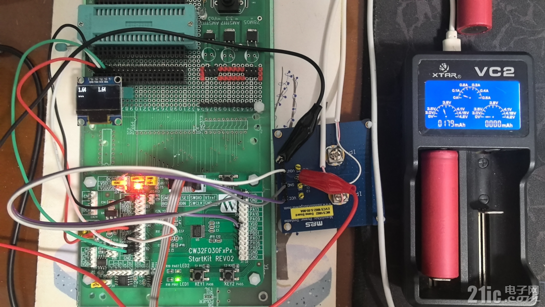
数据差距很小,用万用表测试Vout的电压变化最大在0.2V左右。确实太小了,用来做判断有点困难。为此在程序中加入了特殊处理。在按下开发板Key2按钮时,采集无电池状态下的最大电压数据,作为充电时的比较标准保存下来。按Key1启动充电过程,然后在充电过程中,不断采集Vout,并与之前的最大值比较,如果出现连续10次都低于无电池状态下的最大值,视为充电结束。
在没有电池的状态下,测试验证通过。然后加上电池进行测试。记过整个测试装置工作了一夜,到第二天上午,充电竟然还没有结束。不过这是至少证明了控制充电过程还是比较稳定的。就等充电结束后,是否可以正常结束了。充电过程中,电压最大可达到0.4V的差距,最小的时候和比较标准的最大值一致。

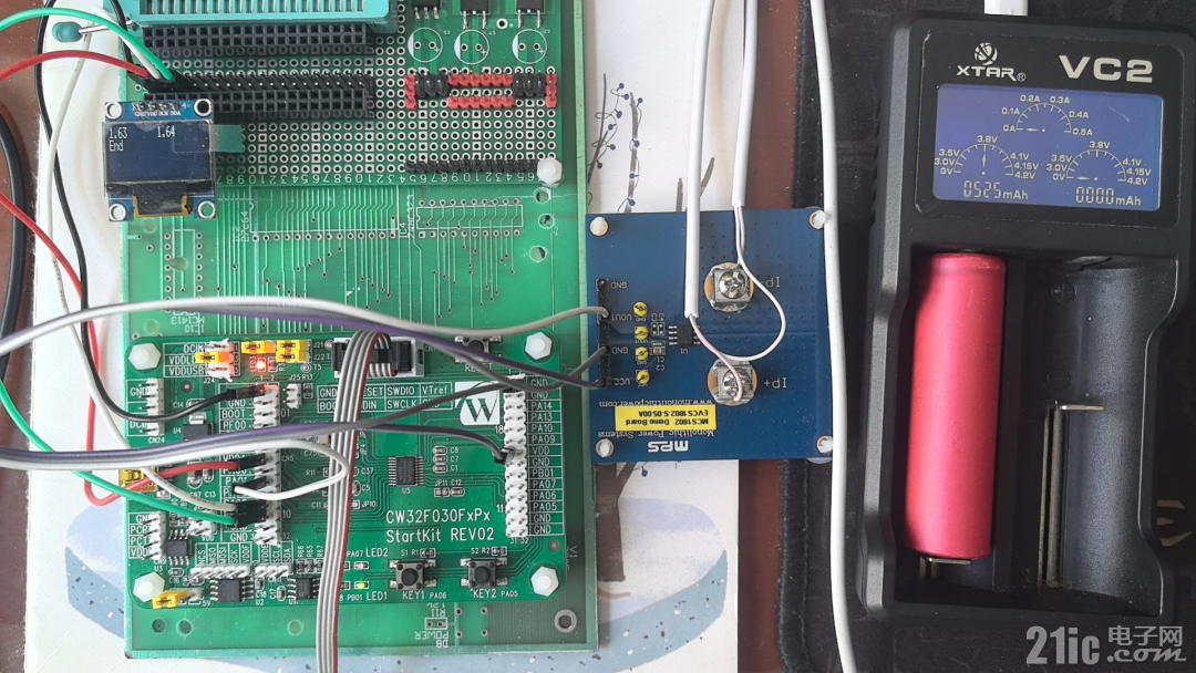
充电结束了,充电器的充电状态结束后,主控板的处理也显示为结束了。
不过有个疑问,为啥加入测试装置以后,充电过程变得如此缓慢了呢?不知道是不是电流检测板影响了充电电流。