本帖最后由 南来之风 于 2025-3-8 13:46 编辑
参考板卡用户手册,了解板卡的默认供电规则。
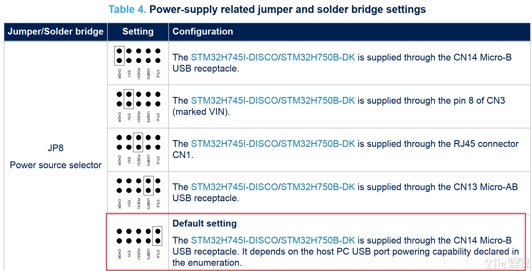
如果固件配置的供电与硬件不一致,会进入dead lock.

点击Create New STM32 Project:

在Example Selector里面选择开发板型号,然后选择一个例程,点击Next:

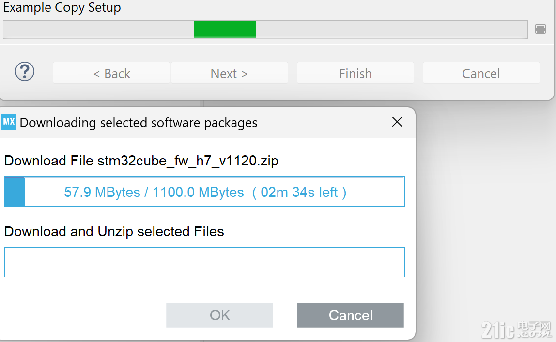
初次搭建环境要从服务器下载H7的BSP
系统时钟配置:
- static void SystemClock_Config(void)
- {
- RCC_ClkInitTypeDef RCC_ClkInitStruct;
- RCC_OscInitTypeDef RCC_OscInitStruct;
- HAL_StatusTypeDef ret = HAL_OK;
- /* The voltage scaling allows optimizing the power consumption when the device is
- clocked below the maximum system frequency, to update the voltage scaling value
- regarding system frequency refer to product datasheet. */
- __HAL_PWR_VOLTAGESCALING_CONFIG(PWR_REGULATOR_VOLTAGE_SCALE1);
- while(!__HAL_PWR_GET_FLAG(PWR_FLAG_VOSRDY)) {}
-
- /* Enable HSE Oscillator and activate PLL with HSE as source */
- RCC_OscInitStruct.OscillatorType = RCC_OSCILLATORTYPE_HSE;
- RCC_OscInitStruct.HSEState = RCC_HSE_ON;
- RCC_OscInitStruct.HSIState = RCC_HSI_OFF;
- RCC_OscInitStruct.CSIState = RCC_CSI_OFF;
- RCC_OscInitStruct.PLL.PLLState = RCC_PLL_ON;
- RCC_OscInitStruct.PLL.PLLSource = RCC_PLLSOURCE_HSE;
- RCC_OscInitStruct.PLL.PLLM = 5;
- RCC_OscInitStruct.PLL.PLLN = 160;
- RCC_OscInitStruct.PLL.PLLFRACN = 0;
- RCC_OscInitStruct.PLL.PLLP = 2;
- RCC_OscInitStruct.PLL.PLLR = 2;
- RCC_OscInitStruct.PLL.PLLQ = 4;
- RCC_OscInitStruct.PLL.PLLVCOSEL = RCC_PLL1VCOWIDE;
- RCC_OscInitStruct.PLL.PLLRGE = RCC_PLL1VCIRANGE_2;
- ret = HAL_RCC_OscConfig(&RCC_OscInitStruct);
- if(ret != HAL_OK)
- {
- Error_Handler();
- }
-
- /* Select PLL as system clock source and configure bus clocks dividers */
- RCC_ClkInitStruct.ClockType = (RCC_CLOCKTYPE_SYSCLK | RCC_CLOCKTYPE_HCLK | RCC_CLOCKTYPE_D1PCLK1 | RCC_CLOCKTYPE_PCLK1 | \
- RCC_CLOCKTYPE_PCLK2 | RCC_CLOCKTYPE_D3PCLK1);
- RCC_ClkInitStruct.SYSCLKSource = RCC_SYSCLKSOURCE_PLLCLK;
- RCC_ClkInitStruct.SYSCLKDivider = RCC_SYSCLK_DIV1;
- RCC_ClkInitStruct.AHBCLKDivider = RCC_HCLK_DIV2;
- RCC_ClkInitStruct.APB3CLKDivider = RCC_APB3_DIV2;
- RCC_ClkInitStruct.APB1CLKDivider = RCC_APB1_DIV2;
- RCC_ClkInitStruct.APB2CLKDivider = RCC_APB2_DIV2;
- RCC_ClkInitStruct.APB4CLKDivider = RCC_APB4_DIV2;
- ret = HAL_RCC_ClockConfig(&RCC_ClkInitStruct, FLASH_LATENCY_4);
- if(ret != HAL_OK)
- {
- Error_Handler();
- }
-
- /*
- Note : The activation of the I/O Compensation Cell is recommended with communication interfaces
- (GPIO, SPI, FMC, QSPI ...) when operating at high frequencies(please refer to product datasheet)
- The I/O Compensation Cell activation procedure requires :
- - The activation of the CSI clock
- - The activation of the SYSCFG clock
- - Enabling the I/O Compensation Cell : setting bit[0] of register SYSCFG_CCCSR
-
- To do this please uncomment the following code
- */
-
- /*
- __HAL_RCC_CSI_ENABLE() ;
-
- __HAL_RCC_SYSCFG_CLK_ENABLE() ;
-
- HAL_EnableCompensationCell();
- */
- }
配置按键中断,通知core m7和core m4
- /**
- * [url=home.php?mod=space&uid=247401]@brief[/url] Configures EXTI lines 15 to 10 (connected to PC.13 pin) in interrupt mode
- * @param None
- * @retval None
- */
- static void EXTI15_10_IRQHandler_Config(void)
- {
- GPIO_InitTypeDef GPIO_InitStructure;
-
- /* Enable GPIOC clock */
- __HAL_RCC_GPIOC_CLK_ENABLE();
-
- /* Configure PC.13 pin as the EXTI input event line in interrupt mode for both CPU1 and CPU2*/
- GPIO_InitStructure.Mode = GPIO_MODE_IT_RISING; /* current CPU (CM7) config in IT rising */
- GPIO_InitStructure.Pull = GPIO_NOPULL;
- GPIO_InitStructure.Pin = GPIO_PIN_13;
- HAL_GPIO_Init(GPIOC, &GPIO_InitStructure);
-
- /* Enable and set EXTI lines 15 to 10 Interrupt to the lowest priority */
- HAL_NVIC_SetPriority(EXTI15_10_IRQn, 2, 0);
- HAL_NVIC_EnableIRQ(EXTI15_10_IRQn);
-
- /* Configure the second CPU (CM4) EXTI line for IT*/
- HAL_EXTI_D2_EventInputConfig(EXTI_LINE13 , EXTI_MODE_IT, ENABLE);
- }
编译成功后,点击Debug Configuration
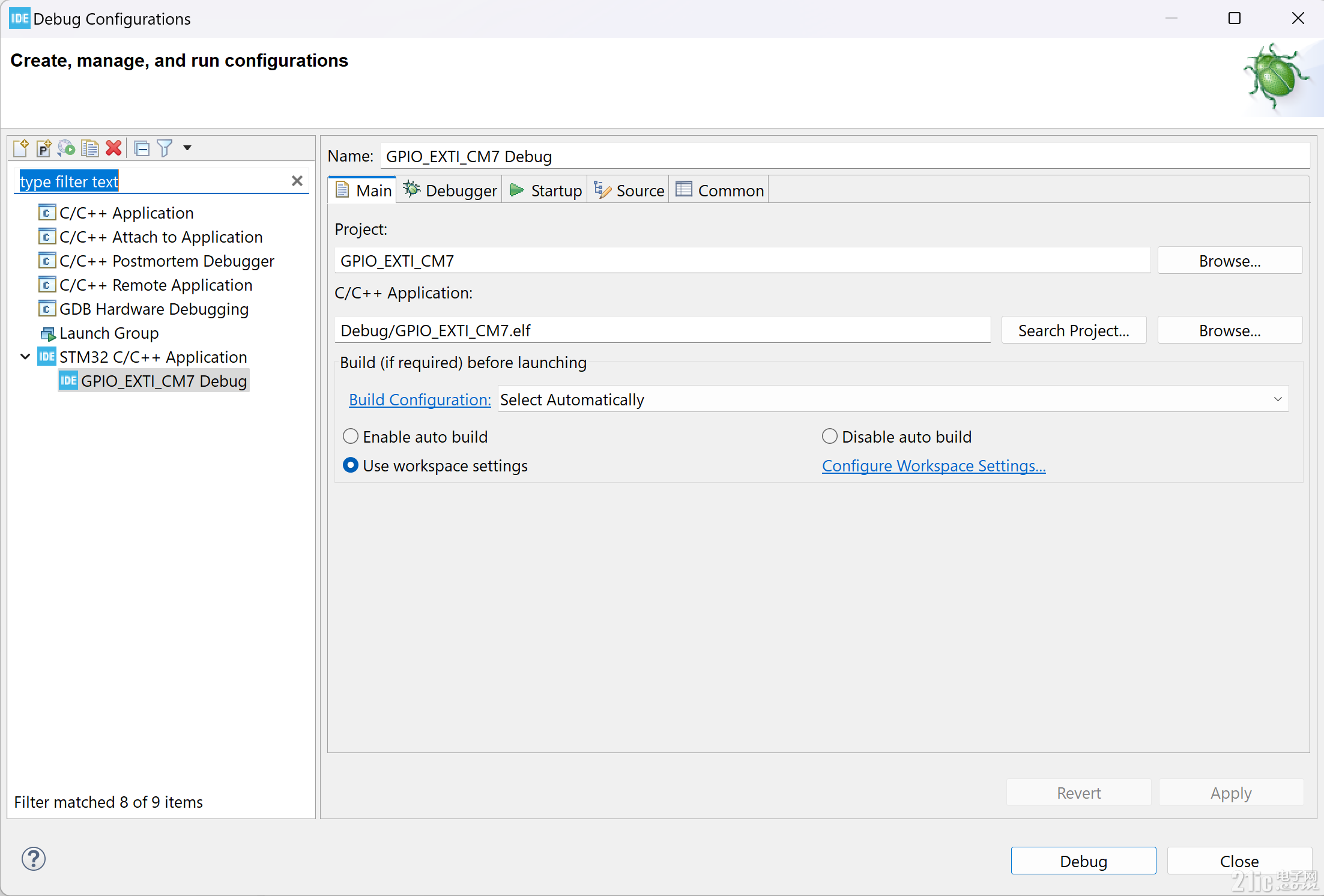
添加Cortex-M4:
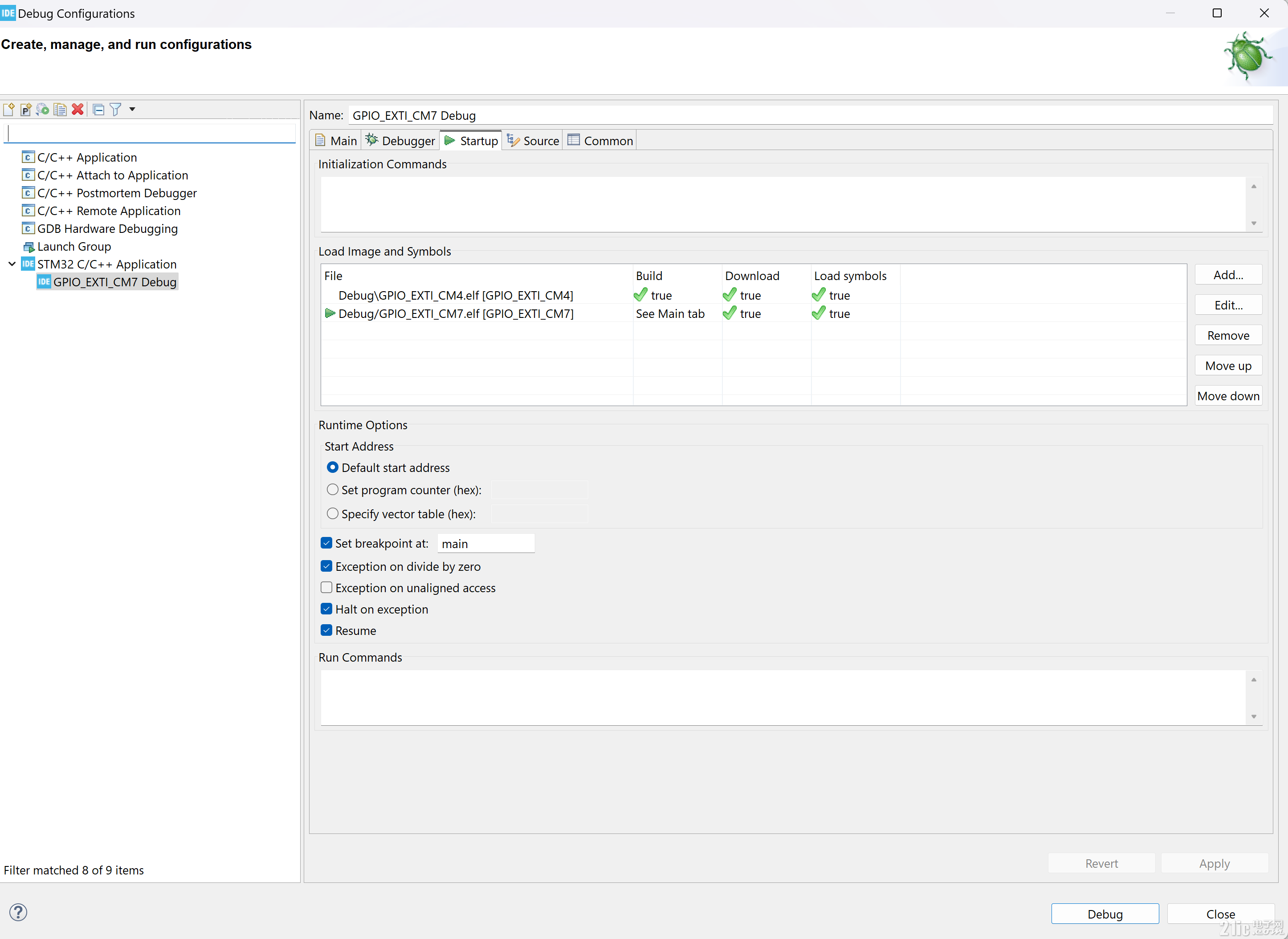
点击Apply, Debug:

升级成功:

成功进入调试界面:
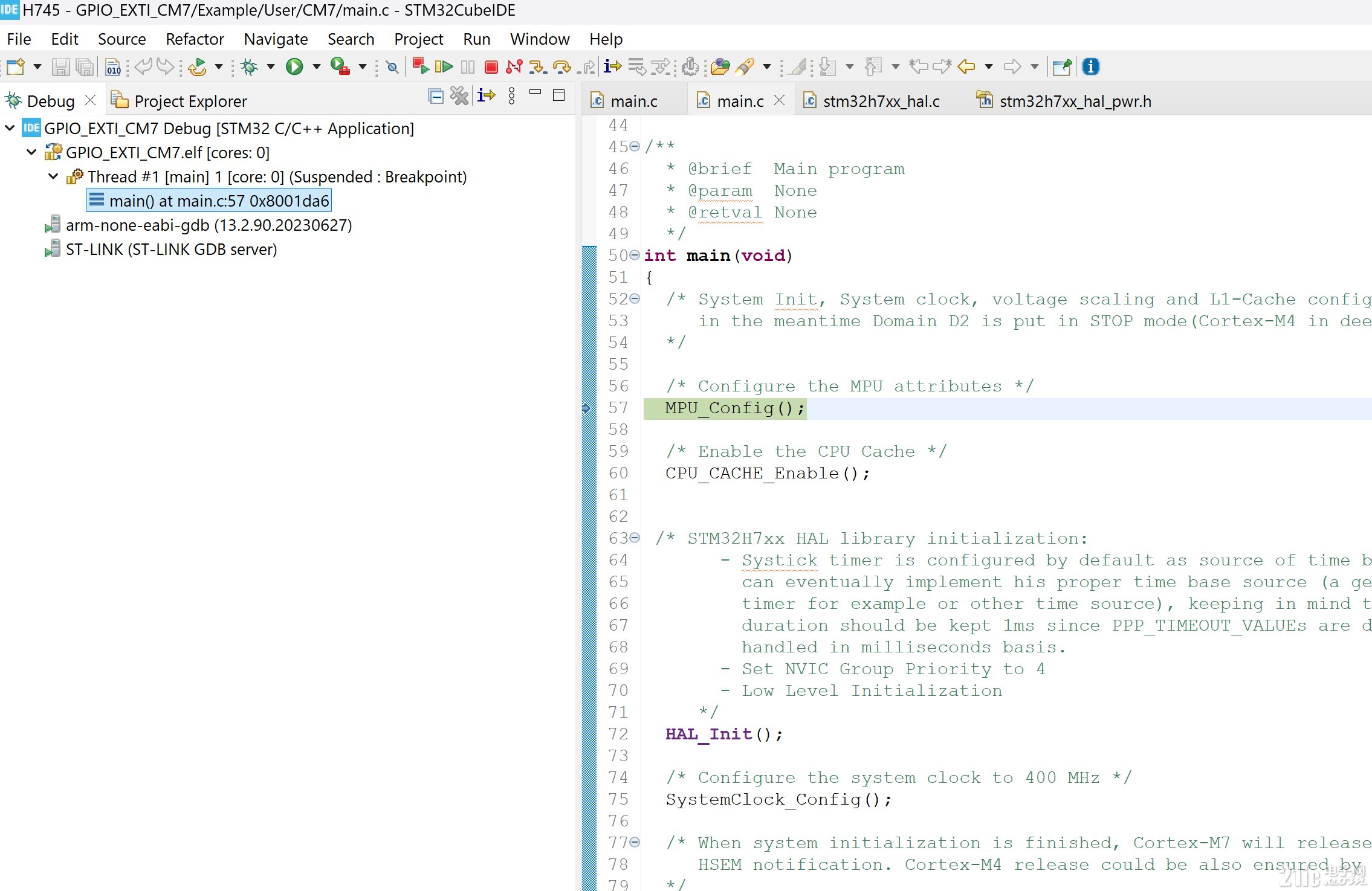
点击全速运行:

点击USER BUTTON 蓝色的按键,小灯状态翻转。
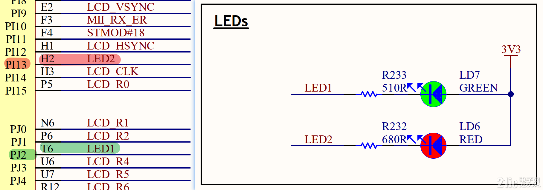
- #define LED1_GPIO_PORT GPIOJ
- #define LED1_PIN GPIO_PIN_2
- #define LED2_GPIO_PORT GPIOI
- #define LED2_PIN GPIO_PIN_13

用户按键没有按下时,红色与绿色led熄灭
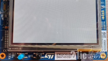
按下后,产生中断,分别在cortex m4与m7中进入中断服务子程序
m7:
- void HAL_GPIO_EXTI_Callback(uint16_t GPIO_Pin)
- {
-
- if (GPIO_Pin == GPIO_PIN_13)
- {
- /* Toggle LED1 */
- BSP_LED_Toggle(LED1);
- }
- }
m4:
- void HAL_GPIO_EXTI_Callback(uint16_t GPIO_Pin)
- {
- if (GPIO_Pin == GPIO_PIN_13)
- {
- /* Toggle LED2 */
- BSP_LED_Toggle(LED2);
- }
- }

|