- void infrared_receiver_init(void)
- {
- gpio_init_type gpio_init_struct;
- tmr_input_config_type tmr_input_config_struct;
- crm_clocks_freq_type crm_clock_freq;
- /* init infrared receiver fifo */
- infrared_receiver_fifo_init();
- /* enable tmr3/gpioa clock */
- crm_periph_clock_enable(IR_TMR_CLK, TRUE);
- crm_periph_clock_enable(IR_GPIO_CLK, TRUE);
- /* timer input pin Configuration */
- gpio_init_struct.gpio_pins = IR_GPIO_PIN;
- gpio_init_struct.gpio_mode = GPIO_MODE_MUX;
- gpio_init_struct.gpio_out_type = GPIO_OUTPUT_PUSH_PULL;
- gpio_init_struct.gpio_pull = GPIO_PULL_NONE;
- gpio_init_struct.gpio_drive_strength = GPIO_DRIVE_STRENGTH_STRONGER;
- gpio_init(IR_GPIO_PORT, &gpio_init_struct);
- gpio_pin_mux_config(IR_GPIO_PORT, IR_GPIO_PINS_SOURCE, IR_GPIO_MUX);
- /* get the system frequency value */
- crm_clocks_freq_get(&crm_clock_freq);
- /* tmr counter mode configuration */
- tmr_base_init(IR_TMRx, 6000, crm_clock_freq.apb1_freq / 1000000);
- tmr_cnt_dir_set(IR_TMRx, TMR_COUNT_UP);
- /* configure tmr channel to get clock signal */
- tmr_input_config_struct.input_channel_select = IR_TMR_CHANNEL;
- tmr_input_config_struct.input_mapped_select = TMR_CC_CHANNEL_MAPPED_DIRECT;
- tmr_input_config_struct.input_polarity_select = TMR_INPUT_RISING_EDGE;
- tmr_input_channel_init(IR_TMRx, &tmr_input_config_struct, TMR_CHANNEL_INPUT_DIV_1);
- /* enable capture interrupt */
- tmr_interrupt_enable(IR_TMRx, IR_TMR_CHANNEL_INT, TRUE);
- /* disable overflow interrupt */
- tmr_interrupt_enable(IR_TMRx, TMR_OVF_INT, FALSE);
- /* interrupt nvic init */
- nvic_irq_enable(IR_TMR_IRQn, 1, 0);
- /* enable tmr */
- tmr_counter_enable(IR_TMRx, TRUE);
- }

4. 编写软件- 初始化定时器捕获:配置定时器和捕获通道。(如前)
- 处理捕获中断:在捕获中断服务程序中读取捕获寄存器的值,并处理这些值以解码红外信号。
- 解码红外信号:根据红外协议(如NEC、Sony、Philips等)解析捕获的时间间隔,以识别按键代码。
定义
- #define IR_GPIO_PORT GPIOB
- #define IR_GPIO_CLK CRM_GPIOB_PERIPH_CLOCK
- #define IR_GPIO_PIN GPIO_PINS_5
- #define IR_GPIO_PINS_SOURCE GPIO_PINS_SOURCE5
- #define IR_GPIO_MUX GPIO_MUX_1
- #define IR_TMRx TMR3
- #define IR_TMR_CLK CRM_TMR3_PERIPH_CLOCK
- #define IR_TMR_CHANNEL TMR_SELECT_CHANNEL_2
- #define IR_TMR_CHANNEL_INT TMR_C2_INT
- #define IR_TMR_CHANNEL_FLAG TMR_C2_FLAG
- #define IR_TMR_IRQn TMR3_GLOBAL_IRQn
- #define IR_TMR_IRQHandler TMR3_GLOBAL_IRQHandler
- #define IR_GPIO_READ() (gpio_input_data_bit_read(IR_GPIO_PORT, IR_GPIO_PIN) != RESET)
中断函数:
- void IR_TMR_IRQHandler(void)
- {
- infrared_receiver_data_deal();
- }
infrared_receiver_data_deal,NEC协议解析:
- void infrared_receiver_data_deal(void)
- {
- uint32_t value;
- static uint32_t ir_data = 0;
- /* input capture event occurs */
- if(tmr_flag_get(IR_TMRx, IR_TMR_CHANNEL_FLAG) != RESET)
- {
- /* clear input capture flag */
- tmr_flag_clear(IR_TMRx, IR_TMR_CHANNEL_FLAG);
- /* clear overflow flag */
- tmr_flag_clear(IR_TMRx, TMR_OVF_FLAG);
- /* enable overflow interrupt */
- tmr_interrupt_enable(IR_TMRx, TMR_OVF_INT, TRUE);
- /* rising edge capture */
- if(IR_GPIO_READ())
- {
- /* clear the counter */
- tmr_counter_value_set(IR_TMRx, 0);
- /* configure capture mode as falling edge capture */
- tmr_output_channel_polarity_set(IR_TMRx, IR_TMR_CHANNEL, TMR_POLARITY_ACTIVE_LOW);
- }
- /* falling edge capture */
- else
- {
- /* get capture counter */
- value = tmr_channel_value_get(IR_TMRx, IR_TMR_CHANNEL);
- /* configure capture mode as rising edge capture */
- tmr_output_channel_polarity_set(IR_TMRx, IR_TMR_CHANNEL, TMR_POLARITY_ACTIVE_HIGH);
- /* received start code */
- if((value > 4200) && (value < 4700))
- {
- ir_data = 0;
- }
- /* received repeat code */
- else if((value > 2000) && (value < 2600))
- {
- /* analysis data */
- infrared_receiver_key_deal(ir_data);
- }
- /* received bit 0 */
- else if((value > 300) && (value < 800))
- {
- ir_data <<= 1;
- }
- /* received bit 1 */
- else if((value > 1400) && (value < 1800))
- {
- ir_data <<= 1;
- ir_data |= 1;
- }
- }
- }
- /* overflow event occurs, 6ms , receive complete */
- else if(tmr_flag_get(IR_TMRx, TMR_OVF_FLAG) != RESET)
- {
- /* clear overflow flag */
- tmr_flag_clear(IR_TMRx, TMR_OVF_FLAG);
- /* disable overflow interrupt */
- tmr_interrupt_enable(IR_TMRx, TMR_OVF_INT, FALSE);
- /* configure capture mode as rising edge capture */
- tmr_output_channel_polarity_set(IR_TMRx, IR_TMR_CHANNEL, TMR_POLARITY_ACTIVE_HIGH);
- /* analysis data */
- infrared_receiver_key_deal(ir_data);
- }
- }
根据接收到的红外数据翻转LED
- if(infrared_receive(&ir_value) == SUCCESS)
- {
- /* display address and cmd */
- printf("address: %d\r\n", (uint8_t)(ir_value >> 8));
- printf("cmd: %d\r\n\r\n", (uint8_t)(ir_value & 0xFF));
-
- switch(ir_value & 0xFF)
- {
- case 224:
- at32_led_toggle(LED2);
- break;
- case 192:
- at32_led_toggle(LED3);
- break;
- case 200:
- at32_led_toggle(LED4);
- break;
- }
- }
5. 运行效果
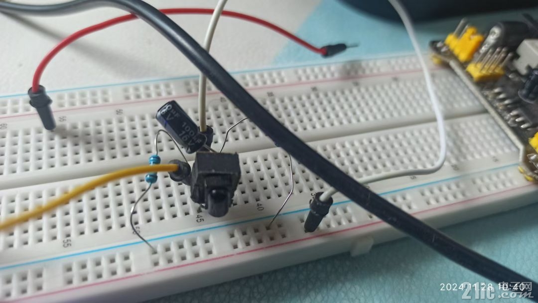
红外接收电路:

红外电路接MCU的PB5、GND

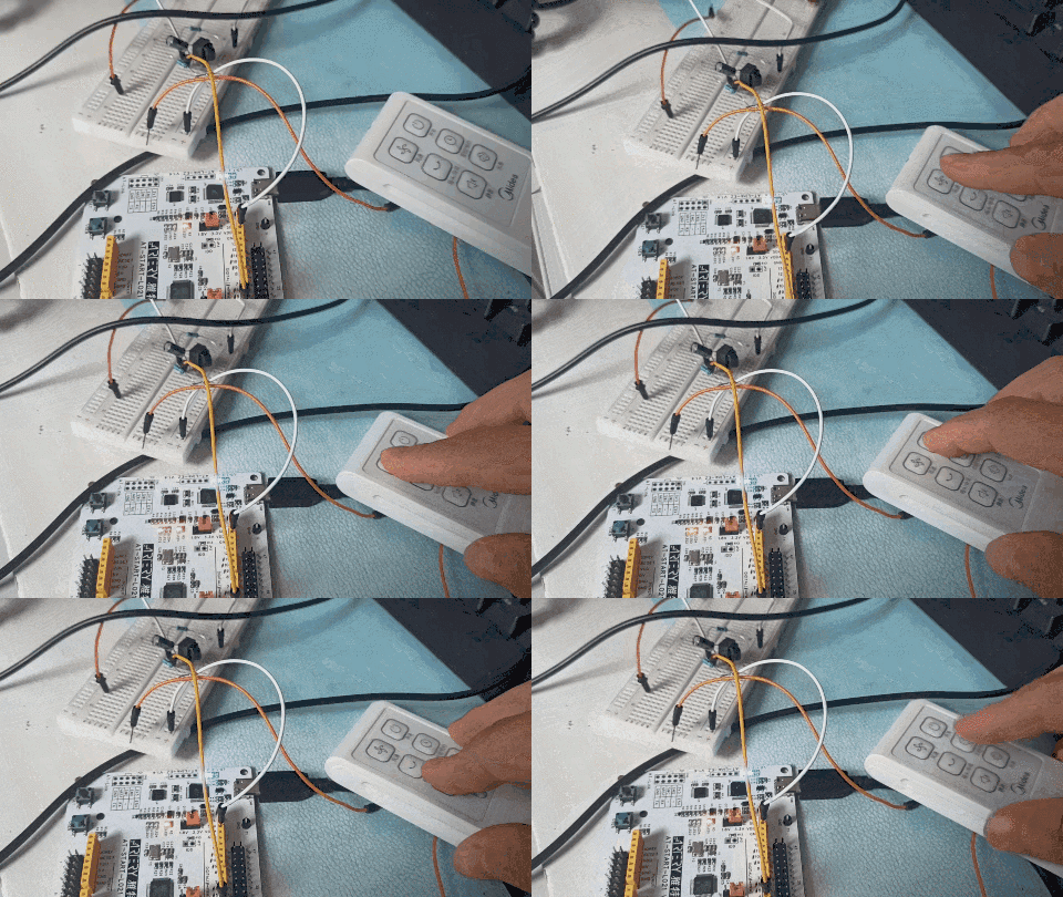
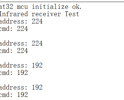
用风扇遥控器做为红外发送器,发送内容固定,前3个键分别对应224、192、200,接收器收到信号后,翻转LED

日志输出:
