- from machine import FPIOA, I2C
- # use hardware i2c
- if HARD_I2C:
- fpioa = FPIOA()
- fpioa.set_function(11, FPIOA.IIC2_SCL)
- fpioa.set_function(12, FPIOA.IIC2_SDA)
- i2c=I2C(2, freq = 400 * 1000)
- print(i2c.scan())
- else:
- # use soft i2c
- i2c=I2C(5, scl = 11, sda = 12, freq = 400 * 1000)
- print(i2c.scan())
- # SSD1306 I2C address (common values: 0x3C or 0x3D)
- OLED_I2C_ADDR = 0x3C
- # Function to send a command to the SSD1306
- def send_command(command):
- # 0x00 indicates we're sending a command (as opposed to data)
- i2c.writeto(OLED_I2C_ADDR, bytearray([0x00, command]))
- # Function to send data (for pixel values) to the SSD1306
- def send_data(data):
- # 0x40 indicates we're sending data (as opposed to a command)
- i2c.writeto(OLED_I2C_ADDR, bytearray([0x40] + data))
- def send_data1(data):
- # 0x00 indicates we're sending data (as opposed to a command)
- i2c.writeto(OLED_I2C_ADDR, bytearray([0x40, data]))
- # SSD1306 Initialization sequence (based on datasheet)
- def oled_init():
- send_command(0xAE) # Display OFF
- send_command(0xA8) # Set MUX Ratio
- send_command(0x3F) # 64MUX
- send_command(0xD3) # Set display offset
- send_command(0x00) # Offset = 0
- send_command(0x40) # Set display start line to 0
- send_command(0xA1) # Set segment re-map (A1 for reverse, A0 for normal)
- send_command(0xC8) # Set COM output scan direction (C8 for reverse, C0 for normal)
- send_command(0xDA) # Set COM pins hardware configuration
- send_command(0x12) # Alternative COM pin config, disable left/right remap
- send_command(0x81) # Set contrast control
- send_command(0x7F) # Max contrast
- send_command(0xA4) # Entire display ON, resume to RAM content display
- send_command(0xA6) # Set Normal display (A6 for normal, A7 for inverse)
- send_command(0xD5) # Set oscillator frequency
- send_command(0x80) # Frequency
- send_command(0x8D) # Enable charge pump regulator
- send_command(0x14) # Enable charge pump
- send_command(0xAF) # Display ON
- # Function to clear the display (turn off all pixels)
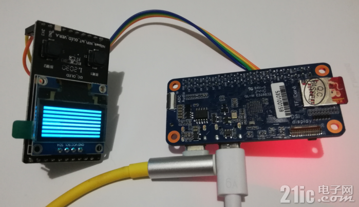
由程序可以得知,显示屏的引脚连接关系为:
SCL-------GPIO11
SDA------GPIO12
经程序运行,其测试效果如图3所示,说明它对显示屏的驱动有效。

图3 驱动测试
为在此基础上实现数据的显示功能,需为其配置字库及相应的显示函数。
其中字库的存储结构为:
F8X16=[
0x00,0x00,0x00,0x00,0x00,0x00,0x00,0x00,0x00,0x00,0x00,0x00,0x00,0x00,0x00,0x00,#0
0x00,0x00,0x00,0xF8,0x00,0x00,0x00,0x00,0x00,0x00,0x00,0x33,0x30,0x00,0x00,0x00,#! 1
0x00,0x10,0x0C,0x06,0x10,0x0C,0x06,0x00,0x00,0x00,0x00,0x00,0x00,0x00,0x00,0x00,#" 2
... ...
}
由于这里采用的编程语言是Python,因此在程序设计时还会与C语言存在一定的差别,有些功能的实现甚至需要绕行来解决。
为进行显示位置的定位,所配置的函数为:
- def OLED_Set_Pos(x, y):
- send_command(0xb0+y)
- send_command(((x&0xf0)>>4)|0x10)
- send_command(x&0x0f)
依托于该函数的支持,实现数字符号显示的函数为:
- def OLED_ShowCharm(x,y,chr):
- c=chr
- OLED_Set_Pos(x,y)
- i=0
- for i in range(8):
- u=F8X16[c*16+i]
- send_data([u]*1)
- OLED_Set_Pos(x,y+1)
- i=0
- for i in range(8):
- u=F8X16[c*16+i+8]
- send_data([u]*1)
为在数据显示过程中,能逐个数位的提取其数值,所配置的函数为:
- def oled_pow( m,n):
- result=1
- while (n>0) :
- n=n-1
- result*=m
- return result
依托前面2个函数的支持,实现数值的函数为:
- def OLED_ShowNum(x,y,num,len):
- enshow=0
- for t in range(len):
- temp=(num/oled_pow(10,len-t-1))%10
- if (enshow==0 & t<(len-1)):
- if(temp>0):
- enshow=1
- OLED_ShowCharm(x+8*t,y,int(temp)+16)
至此,就可以在OLED屏上来实现数据信息了。
为使用RTC来实现电子时钟功能,需导入RTC和time,并对RTC进行实例化,其对应的程序为:
- import time
- from machine import RTC
- # 实例化RTC
- rtc = RTC()
- # 获取当前时间
- print(rtc.datetime())
- # 设置当前时间
- rtc.init((2025,6,28,2,23,59,0,0))
这样就有了实现电子时钟功能的基础,由于 RTC的计时值是以组元的方式来管理数据的,因此读取当前时间后,所显示内容的显示为:
(2025,6,28,2,23,59,0,0)
而这样的显示数据是无法直接拿来实现的,为此需要以如下的方式来提取时间值并予以显示:
z=rtc.datetime()
OLED_ShowNum(0,2,z[4],2)
OLED_ShowNum(24,2,z[5],2)
OLED_ShowNum(48,2,z[6],2)
至此,提供添加下面的循环处理就可为此电子时钟的计时功能:
- # Initialize the OLED display
- oled_init()
- oled_clear()
- OLED_ShowChar(16, 2, 26)
- OLED_ShowChar(40, 2, 26)
- while 1:
- z=rtc.datetime()
- OLED_ShowNum(0,2,z[4],2)
- OLED_ShowNum(24,2,z[5],2)
- OLED_ShowNum(48,2,z[6],2)
- time.sleep(1)
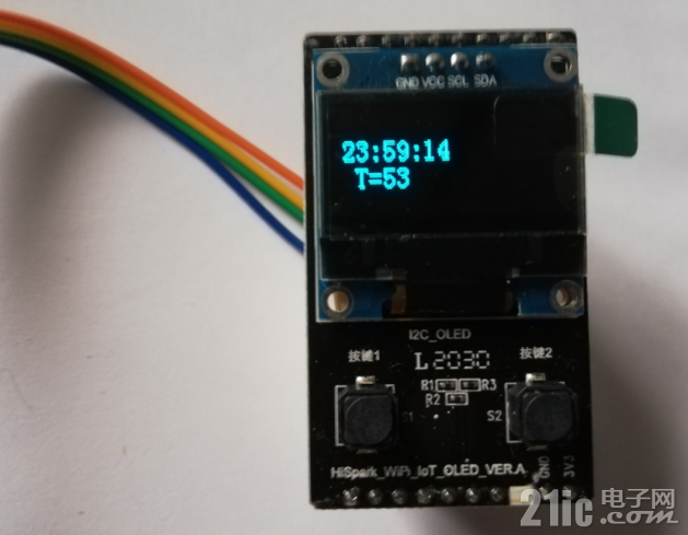
经程序的运行,其显示效果如图4和图5所示。

图4 整体显示效果

图5 详细显示效果
此外,在 os和machine的情况下,还可以对片内温度进行检测,实现电子时钟与片温显示的主程序为:
- import os
- import machine
- # Initialize the OLED display
- oled_init()
- oled_clear()
- OLED_ShowChar(16, 2, 26)
- OLED_ShowChar(40, 2, 26)
- OLED_ShowChar(8, 4, 52)
- OLED_ShowChar(16, 4, 29)
- while True:
- os.exitpoint()
- z=rtc.datetime()
- OLED_ShowNum(0,2,z[4],2)
- OLED_ShowNum(24,2,z[5],2)
- OLED_ShowNum(48,2,z[6],2)
- temp = machine.temperature()
- OLED_ShowNum(24,4,temp,2)
- time.sleep_ms(500)
其执行后,其显示效果如图6所示。

图6 显示效果
为便于字符串的显示,所配置的显示函数为:
- def OLED_ShowString(x,y,chr):
- array1=bytearray(chr, 'utf-8')
- for value in array1:
- OLED_ShowChar(x,y,value-32)
- x+=8
由于系统配置的Python,没有提供获取字符内码的函数,为此是借助bytearray的特点解决了这个问题。
在添加字符串显示功能后,其程序主程序为:
- # Initialize the OLED display
- oled_init()
- oled_clear()
- OLED_ShowChar(26, 3, 26)
- OLED_ShowChar(50, 3, 26)
- OLED_ShowChar(8, 5, 52)
- OLED_ShowChar(16, 5, 29)
- OLED_ShowString(5,0,"BPI-CanMV-K230D")
- while True:
- os.exitpoint()
- z=rtc.datetime()
- OLED_ShowNum(10,3,z[4],2)
- OLED_ShowNum(34,3,z[5],2)
- OLED_ShowNum(58,3,z[6],2)
- temp = machine.temperature()
- OLED_ShowNum(24,5,temp,2)
- #print(f"Temp: {temp}")
- time.sleep_ms(500)
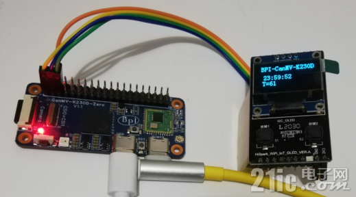
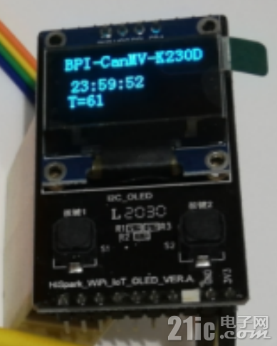
经测试,其显示效果图7和图8所示,说明设计符号预期要求。

图7 整体显示效果

图8 显示效果
演示视频: