AURIX™ Development Studio 简称:ADS . 它是一个免费为初级阶段的开发者提供了简易的开发包的集成开发环境(IDE),包括Eclipse IDE、C编译器、多核调试器、英飞凌低层驱动程序(iLLD),没有时间和代码大小限制,允许编辑、编译和调试应用程序代码。结合大量的代码示例项目,该IDE可以用来评估AURIX™微控制器家族强大的体系结构,方便好用。
官方下载链接:
AURIX™ Development Studio - Infineon Developer Center
- AURIX™ Development Studio环境配置可参考以下链接文档(选择相应的Aurix MCU型号):
Getting Started with AURIX™ Development Studio Installation and first steps (infineon.com)
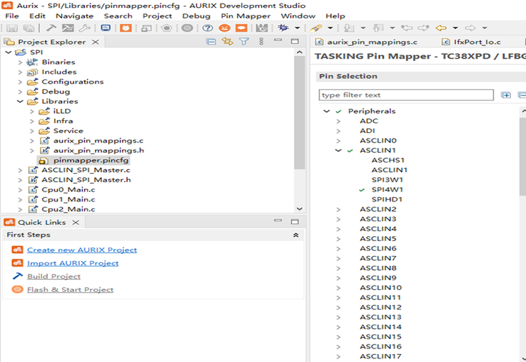
3.PinMap设定:
第一步:使用ASCLIN的SPI功能,将CS(P20.8),SCL(P20.8), MOSI(P15.0) MISO(P15.1), ERUIN0(P10.7), ERUIN0(P10.8)对应MCU引脚设定好.
、
第二步:对原厂iLLD提供的IfxAsclin_Spi.h做一下接口的参数封装代码如下
SCLIN_SPI_Master.h
#ifndef ASCLIN_SPI_MASTER_H _
#define ASCLIN_SPI_MASTER_H_
void init_ASCLIN_SPI_master(void);
void exchange_ASCLIN_SPI_message(void);
#endif /* ASCLIN_SPI_MASTER_H_ */
ASCLIN_SPI_Master.C
#include "IfxAsclin_Spi.h"
/*********************************************************************************************************************/
/*------------------------------------------------------Macros-------------------------------------------------------*/
/*********************************************************************************************************************/
#define SPI_BUFFER_SIZE 2 /* Size of the SPI buffer in bytes */
#define BAUDRATE 115200 /* Define baud rate in bit/s */
#define PRESCALER 1 /* Define prescaler */
#define IFX_INTPRIO_ASCLIN1_TX 1 /* Define TX interrupt priority */
#define IFX_INTPRIO_ASCLIN1_RX 2 /* Define RX interrupt priority */
#define CLOCK_PIN IfxAsclin1_SCLK_P20_10_OUT /* Define Clock port pin */
#define MTSR_PIN IfxAsclin1_TX_P15_0_OUT /* Define MTSR port pin */
#define MRST_PIN IfxAsclin1_RXA_P15_1_IN /* Define MRST port pin */
#define CS1_PIN IfxAsclin1_SLSO_P20_8_OUT /* DefineCS1 port pin */
/*********************************************************************************************************************/
/*-------------------------------------------------Global variables--------------------------------------------------*/
/*********************************************************************************************************************/
IfxAsclin_Spi g_spiHandle;
uint8 g_spiTxBuffer[] = {0X20,0};
uint8 g_spiRxBuffer[SPI_BUFFER_SIZE];
uint8 Read1;
uint8 Write1;
/*********************************************************************************************************************/
/*---------------------------------------------Function Implementations----------------------------------------------*/
/*********************************************************************************************************************/
/* Add SPI Interrupt Service Routines */
IFX_INTERRUPT(asclin1TxISR, 0, IFX_INTPRIO_ASCLIN1_TX);
/* Transmit interrupt function */
void asclin1TxISR(void)
{
IfxAsclin_Spi_isrTransmit(&g_spiHandle);
}
IFX_INTERRUPT(asclin1RxISR, 0, IFX_INTPRIO_ASCLIN1_RX);
/* Receive interrupt function */
void asclin1RxISR(void)
{
IfxAsclin_Spi_isrReceive(&g_spiHandle);
}
/* This function initializes the ASCLIN SPI module in master mode */
void init_ASCLIN_SPI_master(void)
{
/* Initialize one instance of IfxAsclin_Spi_Config with default values */
IfxAsclin_Spi_Config spiMasterConfig;
IfxAsclin_Spi_initModuleConfig(&spiMasterConfig, &MODULE_ASCLIN1);
/* Set the desired baud rate */
spiMasterConfig.baudrate.prescaler = PRESCALER;
spiMasterConfig.baudrate.baudrate = BAUDRATE;
/* ISR priorities and service provider */
spiMasterConfig.interrupt.txPriority = IFX_INTPRIO_ASCLIN1_TX;
spiMasterConfig.interrupt.rxPriority = IFX_INTPRIO_ASCLIN1_RX;
spiMasterConfig.interrupt.typeOfService = IfxSrc_Tos_cpu0;
/* Pin configuration */
const IfxAsclin_Spi_Pins pins =
{
&CLOCK_PIN, IfxPort_OutputMode_pushPull, /* Clock output port pin (CLK) */
&MRST_PIN, IfxPort_InputMode_pullUp, /* MRST port pin (MISO) */
&MTSR_PIN, IfxPort_OutputMode_pushPull, /* MTSR port pin (MOSI) */
&CS1_PIN , IfxPort_OutputMode_pushPull, /* cs1 port pin (cs1) */
IfxPort_PadDriver_cmosAutomotiveSpeed4
};
spiMasterConfig.pins = &pins;
/* Initialize module with the above parameters */
IfxAsclin_Spi_initModule(&g_spiHandle, &spiMasterConfig);
}
/* This function exchanges a two bytes message */
void exchange_ASCLIN_SPI_message(void)
{
/* Exchange the two bytes message */
IfxAsclin_Spi_exchange(&g_spiHandle, g_spiTxBuffer,g_spiRxBuffer, SPI_BUFFER_SIZE);
}
第三步:写传感器寄存器访问逻辑(读IIS3DWB寄存器地址20H和21H的值)
Cpu0_Main.c
#include "Ifx_Types.h"
#include "IfxCpu.h"
#include "IfxScuWdt.h"
#include "Ifx_Types.h"
#include "IfxCpu.h"
#include "IfxScuWdt.h"
#include "ASCLIN_SPI_Master.h"
#include "Bsp.h"
extern uint8 g_spiTxBuffer[]; /*Link Transmit TX message buffer */
extern uint8 g_spiRxBuffer[]; /*Link Receive RX message buffer */
uint8 RX1L;
uint8 RX1H;
IFX_ALIGN(4) IfxCpu_syncEvent g_cpuSyncEvent = 0;
void core0_main(void)
{
IfxCpu_enableInterrupts();
/* !!WATCHDOG0 AND SAFETY WATCHDOG ARE DISABLED HERE!!
* Enable the watchdogs and service them periodically if it is required
*/
IfxScuWdt_disableCpuWatchdog(IfxScuWdt_getCpuWatchdogPassword());
IfxScuWdt_disableSafetyWatchdog(IfxScuWdt_getSafetyWatchdogPassword());
/* Wait for CPU sync event */
IfxCpu_emitEvent(&g_cpuSyncEvent);
IfxCpu_waitEvent(&g_cpuSyncEvent, 1);
init_ASCLIN_SPI_master();/*Initialized SPI */
while(1)
{
g_spiTxBuffer[0]=0x20U; /* Assign access address 20H*/
exchange_ASCLIN_SPI_message(); /*Sent the address& get data */
RX1L= g_spiRxBuffer[0]; /*Get Sensor Low 8 bit data */
waitTime(1000000);
g_spiTxBuffer[0]=0x21U; /* Assign access address 21H*/
exchange_ASCLIN_SPI_message();
RX1H= g_spiRxBuffer[0]; /*Get Sensor High 8 bit data */
DATA=RX1H<<8|RX1L; /*High and low 8-bit data merge */
waitTime(100000000); /*Wait time for next */
}
}
第四步:编译及Flash写入程序:
第五步:启动程序调试,用示波器或逻辑分析仪检测查看波形
(黄色为CS,绿色为主机输出)
(黄色主机发送,绿色主机接收,相位没调,实际相差8个bit时间)


 楼主
楼主


