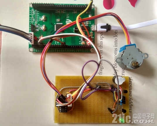
NV32F100开发板驱动的步进电机型号为28BYJ-48,由于其工作电流相对较大,故需要配相应的驱动芯片,这里选用的芯片为ULN2003,整体电路如图所示。

1.驱动芯片ULN2003 ULN2003驱动芯片由7组达林顿电路构成,其中的每一组达林顿电路都串联一个2.7K 的基极电阻,在5V 的工作电压下它能与TTL 和CMOS 电路直接相连,可以直接处理原先需要标准逻辑缓冲器来处理的数据。 ULN2003 工作电压高,工作电流大,灌电流可达500mA,并且能够在关态时承受50V 的电压,输出还可以在高负载电流并行运行。

2. 4相5线制步进电机 28BYJ-48是4相5线制减速步进电机,它共有5条引线,其中VCC接电机的中心抽头线(一般为红色),其它4条接电机的A,B,C,D相。该电机的直径为28mm,电压:5V,步进角度:5.625 x 1/64,减速比:1/64。

3.步进电机控制 为使开发板控制步进电机的转动,其相应引脚的定义如下: A -- PH1 B -- PH0 C -- PE0 D -- PE1 步进电机正反转的程序如下:
- #include "common.h"
- #include "ics.h"
- #include "rtc.h"
- #include "uart.h"
- #include "gpio.h"
- #include "sysinit.h"
- #include "start.h"
- #include "adc.h"
- #define MAH GPIO_PinSet(GPIO_PTH1);
- #define MAL GPIO_PinClear(GPIO_PTH1);
- #define MBH GPIO_PinSet(GPIO_PTH0);
- #define MBL GPIO_PinClear(GPIO_PTH0);
- #define MCH GPIO_PinSet(GPIO_PTE0);
- #define MCL GPIO_PinClear(GPIO_PTE0);
- #define MDH GPIO_PinSet(GPIO_PTE1);
- #define MDL GPIO_PinClear(GPIO_PTE1);
- long int delay_1us(void)
- {
- long int count=2;
- while(count--);
- return 0;
- }
- void delay_ms(uint16_t nms)
- {
- uint16_t n,m;
- n=nms;
- while(n)
- {
- for(m=0;m<1000;m++) delay_1us();
- n--;
- }
- }
- int main (void)
- {
- uint16_t X,Y;
- sysinit();
- cpu_identify();
- //步进电机控制引脚初始化
- GPIO_Init(GPIOB, GPIO_PTE7_MASK, GPIO_PinOutput);
- GPIO_Init(GPIOB, GPIO_PTE7_MASK, GPIO_PinOutput);
- GPIO_Init(GPIOB, GPIO_PTE0_MASK, GPIO_PinOutput);
- GPIO_Init(GPIOB, GPIO_PTE1_MASK, GPIO_PinOutput);
- GPIO_Init(GPIOB, GPIO_PTH0_MASK, GPIO_PinOutput);
- GPIO_Init(GPIOB, GPIO_PTH1_MASK, GPIO_PinOutput);
- //正转2周
- MAL;
- MBL;
- MCL;
- MDL;
- for(X=0;X<192;X++)
- {
- for(Y=0;Y<8;Y++)
- {
- MDL;
- MAH; //A
- delay_ms(1);
- MBH; //AB
- delay_ms(1);
- MAL; //B
- delay_ms(1);
- MCH; //BC
- delay_ms(1);
- MBL; //C
- delay_ms(1);
- MDH; //CD
- delay_ms(1);
- MCL; //D
- delay_ms(1);
- MAH; //DA
- delay_ms(1);
- }
- }
- delay_ms(100);
- //反转2周
- for(X=0;X<192;X++)
- {
- for(Y=0;Y<8;Y++)
- {
- MDH;
- MAH; //A
- delay_ms(1);
- MAL; //AB
- delay_ms(1);
- MCH; //B
- delay_ms(1);
- MDL; //BC
- delay_ms(1);
- MBH; //C
- delay_ms(1);
- MCL; //CD
- delay_ms(1);
- MAH; //D
- delay_ms(1);
- MBL; //DA
- delay_ms(1);
- }
- }
- while(1);
- }
|