- #include<stdio.h>
- int main(void)
- {
- int SEG[29]={3,7,6,5,4,58,26,27,30,-1,-1,35,40,0,1,8,9,10,11,15,16,17,-1,20,19,22,21,28,29};
- int COM[4] ={35,40,0,1};
- int Pxy[4][29];
- int x=0,y=0,i=0;
- unsigned int DR[8];
- /*SEG段码对应线设置,该板子为4个COM加2个SEG表示一组显示内容*/
- int segch1=4,segch2=5;
- for(i=0;i<8;i++) DR[i]=0;
- for(x=0;x<4;x++)
- for(y=0;y<29;y++)
- Pxy[x][y]=0;
- /*下面为显示矩阵,填写1的表示被选中*/
- Pxy[0][segch1]=1; Pxy[0][segch2]=1;
- Pxy[1][segch1]=1; Pxy[1][segch2]=1;
- Pxy[2][segch1]=1; Pxy[2][segch2]=1;
- Pxy[3][segch1]=1; Pxy[3][segch2]=1;
- for(x=0;x<4;x++)
- {
- for(y=segch1;y<segch2+1;y++)
- {
- if(Pxy[x][y]==1)
- {
- {
- if(COM[x]>=32) DR[(2*x)+1] |= (1<<(COM[x]-32));
- else if(COM[x]>=0) DR[2*x] |= (1<<COM[x]);
- else printf("COM[x] is error!");
- }
- {
- if(SEG[y]>=32) DR[2*x+1] |= (1<<(SEG[y]-32));
- else if(SEG[y]>=0) DR[2*x] |= (1<<SEG[y]);
- else printf("SEG[y] is error!");
- }
- }
- }
- }
- /*输出对应的显示寄存器值*/
- for(i=0;i<8;i++)
- printf("DR[%d]=%d\n",i,DR[i]);
- return 0;
- }

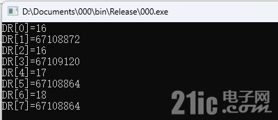
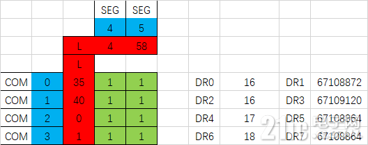
这与我Excel工具计算的结果是一致的。

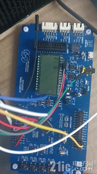
接下来利用单片机来显示一个计数的方法,由于我们可以全部点亮所有的段,因此可以实现静态点亮LCD数码管,这比循环点亮的LED段码管好用多了。
- /*
- * Copyright 2022 MindMotion Microelectronics Co., Ltd.
- * All rights reserved.
- *
- * SPDX-License-Identifier: BSD-3-Clause
- */
- #include "board_init.h"
- #include "lcd.h"
- /*
- * Macros.
- */
- #define APP_SLCD_SEG_BITS_BUFF_LEN 2u
- /*
- * Variables.
- */
- volatile uint32_t app_slcd_seg_bits[APP_SLCD_SEG_BITS_BUFF_LEN];
- const uint32_t app_slcd_com_pin_buff[BOARD_SLCD_COM_NUM] = {BOARD_SLCD_COM_PIN_BUFF};
- const uint32_t app_slcd_seg_pin_buff[BOARD_SLCD_SEG_NUM] = {BOARD_SLCD_SEG_PIN_BUFF};
- /*
- * Declerations.
- */
- void app_delay(uint32_t delay);
- void app_slcd_init(void);
- /*
- * Functions.
- */
- int main(void)
- {
- int i=0,j=0,x1,x2,x3,x4;
- int ch[4]={0};
- BOARD_Init();
- app_slcd_init();
-
- uint32_t BOARD_SLCD_COM[BOARD_SLCD_COM_NUM]={BOARD_SLCD_COM_PIN_BUFF};
- uint32_t BOARD_SLCD_SEG[BOARD_SLCD_SEG_NUM]={BOARD_SLCD_SEG_PIN_BUFF};
- x1=0;
- x2=1;
- x3=2;
- x4=3;
- while (1)
- {
- for(i=0;i<1999;i++)
- {
- ch[0]=i/1000;
- ch[1]=(i%1000)/100;
- ch[2]=(i%100)/10;
- ch[3]=i%10;
-
- // COM0
- BOARD_SLCD_PORT->DR0 =TAB[x1][ch[0]][0]|TAB[x2][ch[1]][0]|TAB[x3][ch[2]][0]|TAB[x4][ch[3]][0];
- BOARD_SLCD_PORT->DR1 =TAB[x1][ch[0]][1]|TAB[x2][ch[1]][1]|TAB[x3][ch[2]][1]|TAB[x4][ch[3]][1];
- // COM1
- BOARD_SLCD_PORT->DR2 =TAB[x1][ch[0]][2]|TAB[x2][ch[1]][2]|TAB[x3][ch[2]][2]|TAB[x4][ch[3]][2];
- BOARD_SLCD_PORT->DR3 =TAB[x1][ch[0]][3]|TAB[x2][ch[1]][3]|TAB[x3][ch[2]][3]|TAB[x4][ch[3]][3];
- // COM2
- BOARD_SLCD_PORT->DR4 =TAB[x1][ch[0]][4]|TAB[x2][ch[1]][4]|TAB[x3][ch[2]][4]|TAB[x4][ch[3]][4];
- BOARD_SLCD_PORT->DR5 =TAB[x1][ch[0]][5]|TAB[x2][ch[1]][5]|TAB[x3][ch[2]][5]|TAB[x4][ch[3]][5];
- // COM3
- BOARD_SLCD_PORT->DR6 =TAB[x1][ch[0]][6]|TAB[x2][ch[1]][6]|TAB[x3][ch[2]][6]|TAB[x4][ch[3]][6];
- BOARD_SLCD_PORT->DR7 =TAB[x1][ch[0]][7]|TAB[x2][ch[1]][7]|TAB[x3][ch[2]][7]|TAB[x4][ch[3]][7];
- app_delay(20u);
-
- }
- }
- }
- void app_slcd_init(void)
- {
- /* Setup the SLCD engine. */
- SLCD_Init_Type slcd_init;
- slcd_init.ClockDiv0 = BOARD_SLCD_DIV0;
- slcd_init.ClockDiv1 = BOARD_SLCD_DIV1;
- slcd_init.ChargePumpClockDiv = BOARD_SLCD_CHARGEPUMPDIV;
- slcd_init.DutyCycle = BOARD_SLCD_DUTYCYCLE;
- slcd_init.BiasMode = BOARD_SLCD_BIASMODE;
- slcd_init.PowerSource = SLCD_PowerSource_Internal;
- slcd_init.ChargePumpMode = SLCD_ChargePumpMode_Boost;
- slcd_init.Brightness = BOARD_SLCD_BRIGHTNESS;
- slcd_init.EnableLowPowerMode = false;
- SLCD_Init(BOARD_SLCD_PORT, &slcd_init);
- /* Set common pin. */
- for (uint32_t com_x = 0; com_x < BOARD_SLCD_COM_NUM; com_x++)
- {
- SLCD_SetCOMxPinMux(BOARD_SLCD_PORT, com_x, app_slcd_com_pin_buff[com_x]);
- }
- /* Set segment pin. */
- for (uint32_t seg_y = 0; seg_y < BOARD_SLCD_SEG_NUM; seg_y++)
- {
- SLCD_SetSegBitPinMux(BOARD_SLCD_PORT, app_slcd_seg_pin_buff[seg_y]);
- }
- /* Enable SLCD. */
- SLCD_Enable(BOARD_SLCD_PORT, true);
- }
- void app_delay(uint32_t delay)
- {
- for (uint32_t i = 0u; i < delay; i++)
- {
- for (uint32_t j = 0u; j < BOARD_DELAY_COUNT; j++)
- {
- __NOP();
- }
- }
- }
- /* EOF. */

显示对比度修改
#define BOARD_SLCD_BRIGHTNESS 10u
官方提供的扫线测试程序默认为5u,我这里修改成10u显示效果非常好。