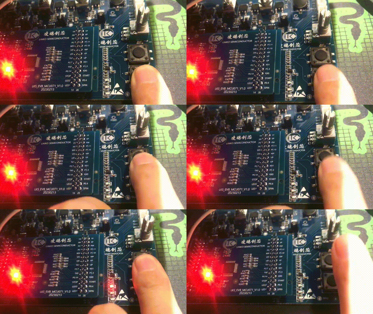
- #define KEY_GPIO GPIO2
- #define KEY1_PIN GPIO_Pin_11
- #define KEY2_PIN GPIO_Pin_12
- #define KEY_PINS KEY1_PIN|KEY2_PIN
- void key_init()
- {
- GPIO_InitTypeDef GPIO_InitStruct;
- GPIO_StructInit(&GPIO_InitStruct);
- GPIO_StructInit(&GPIO_InitStruct);
- GPIO_InitStruct.GPIO_Mode = GPIO_Mode_IN;
- GPIO_InitStruct.GPIO_Pin = KEY_PINS;
- GPIO_Init(KEY_GPIO, &GPIO_InitStruct);
- }
- void mcu_init(void)
- {
- __disable_irq(); /* 关闭中断 中断总开关 */
- SYS_WR_PROTECT = 0x7a83; /*使能系统寄存器写操作*/
- FLASH_CFG |= 0x00080000; /* enable prefetch ,FLASH预取加速使能*/
- IWDG_DISABLE(); /*关闭清零看门狗*/
- SYS_MclkChoice(SYS_MCLK_96M_RC); /*选择当前主时钟频率*/
- SysClock = SYS_ReadMcuClk();
- led_init();
- key_init();
- yuyy_delay_us(100); /* 延时等待硬件初始化稳定 */
- SYS_WR_PROTECT = 0x0; /*关闭系统寄存器写操作*/
- __enable_irq(); /* 开启总中断 */
- }
- int main(void)
- {
- mcu_init();
- while (1)
- {
- if(Bit_RESET == GPIO_ReadInputDataBit(KEY_GPIO,KEY1_PIN))
- GPIO_SetBits(LED_GPIO, LED1_PIN);
- else
- GPIO_ResetBits(LED_GPIO, LED1_PIN);
-
- if(Bit_RESET == GPIO_ReadInputDataBit(KEY_GPIO,KEY2_PIN))
- GPIO_SetBits(LED_GPIO, LED2_PIN);
- else
- GPIO_ResetBits(LED_GPIO, LED2_PIN);
- }
- }
4.2 PWM输出
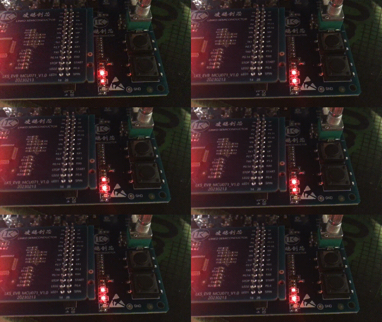
通过使用Timer的比较模式可以输出PWM,查看原理图,LED1和LED2的引脚正好是Timer1两个通道的输出,用这两个LED写个呼吸灯测试一下PWM输出功能

工程需添加库文件lks32mc07x_tim.c
代码示例
- void pwm_gpio_init()
- {
- GPIO_InitTypeDef GPIO_InitStruct;
- GPIO_StructInit(&GPIO_InitStruct); //初始化结构体
- //配置P0.6 UTIMER1_CH0 配置P0.7 UTIMER1_CH1
- GPIO_InitStruct.GPIO_Mode = GPIO_Mode_OUT; //GPIO输出模式
- GPIO_InitStruct.GPIO_Pin = GPIO_Pin_6|GPIO_Pin_7;
- GPIO_Init(GPIO0, &GPIO_InitStruct);
- GPIO_PinAFConfig(GPIO0,GPIO_PinSource_6,AF7_TIMER01); //P0.6复用为timer1的输出模式
- GPIO_PinAFConfig(GPIO0,GPIO_PinSource_7,AF7_TIMER01); //P0.7复用为timer1的输出模式
- }
- void pwm_utimer_init(void)
- {
- TIM_TimerInitTypeDef TIM_InitStruct;
- TIM_TimerStrutInit(&TIM_InitStruct); /* Timer结构体初始化*/
- TIM_InitStruct.Timer_CH0_WorkMode = TIMER_OPMode_CMP; /* 设置Timer CH0 为比较模式 */
- TIM_InitStruct.Timer_CH0Output = 0; /* 计数器回零时,比较模式输出极性控制 */
- TIM_InitStruct.Timer_CH1_WorkMode = TIMER_OPMode_CMP; /* 设置Timer CH1 为比较模式 */
- TIM_InitStruct.Timer_CH1Output = 0; /* 计数器回零时,比较模式输出极性控制 */
- TIM_InitStruct.Timer_TH = 6000; /* 定时器计数门限初始值6000*/
- TIM_InitStruct.Timer_CMP0 = 0; /* 设置比较模式的CH0比较初始值0 */
- TIM_InitStruct.Timer_CMP1 = 0; /* 设置比较模式的CH1比较初始值0 */
- TIM_InitStruct.Timer_FLT = 0; /* 设置捕捉模式或编码器模式下对应通道的数字滤波值 */
- TIM_InitStruct.Timer_ClockDiv = TIMER_CLK_DIV16; /* 设置Timer模块时钟分频系数 */
- TIM_TimerInit(UTIMER1, &TIM_InitStruct);
- TIM_TimerCmd(UTIMER1, ENABLE); /* Timer1 模块使能 */
- }
- void mcu_init(void)
- {
- __disable_irq(); /* 关闭中断 中断总开关 */
- SYS_WR_PROTECT = 0x7a83; /*使能系统寄存器写操作*/
- FLASH_CFG |= 0x00080000; /* enable prefetch ,FLASH预取加速使能*/
- IWDG_DISABLE(); /*关闭清零看门狗*/
- SYS_MclkChoice(SYS_MCLK_96M_RC); /*选择当前主时钟频率*/
- SysClock = SYS_ReadMcuClk();
- pwm_gpio_init();
- pwm_utimer_init();
- yuyy_delay_us(100); /* 延时等待硬件初始化稳定 */
- SYS_WR_PROTECT = 0x0; /*关闭系统寄存器写操作*/
- __enable_irq(); /* 开启总中断 */
- }
- int main(void)
- {
- uint16_t pwm = 0;
- uint8_t dir = 0;
- mcu_init();
- while (1)
- {
- if(dir == 0)
- {
- pwm++;
- if(pwm == 6000)
- dir = 1;
- }
- else
- {
- pwm--;
- if(pwm == 0)
- dir = 0;
- }
- TIM_CMP0(UTIMER1,pwm);
- TIM_CMP1(UTIMER1,6000-pwm);
- yuyy_delay_us(200);
- }
- }
4.3 SPI驱动LCD屏幕
LKS32MC071有一路 SPI,支持主从模式,手里有个12864的LCD屏幕可以用SPI驱动
驱动这个屏幕需要用到5个IO CS RST A0 SCK MOSI,在原理图上尽量找没有被用到的IO
P0.14作为SPI_SCK P2.10作为SPI_MOSI P2.3作为CS P2.2作为RST P3.2作为A0

工程需添加库文件lks32mc07x_spi.c

代码示例,只列出了适配部分的代码
- #include "yuyy_hs12864g18b_spi.h"
- #include "yuyy_delay.h"
- #include "lks32mc07x_gpio.h"
- #if(!YUYY_HS12864G18B_USE_SOFT_SPI)
- #include "lks32mc07x_spi.h"
- #endif
- //spi1 mosi P2.10
- //spi1 clk P0.14
- //CSPIN P2.3
- //RSTPIN P2.2
- //A0PIN P3.2
- #define HS12864G18B_SPI_MOSI(x) x==YUYY_GPIO_LEV0?GPIO_ResetBits(GPIO2,GPIO_Pin_10):GPIO_SetBits(GPIO2,GPIO_Pin_10)
- #define HS12864G18B_SPI_SCK(x) x==YUYY_GPIO_LEV0?GPIO_ResetBits(GPIO0,GPIO_Pin_14):GPIO_SetBits(GPIO0,GPIO_Pin_14)
- #define HS12864G18B_SPI_CS(x) x==YUYY_GPIO_LEV0?GPIO_ResetBits(GPIO2,GPIO_Pin_3):GPIO_SetBits(GPIO2,GPIO_Pin_3)
- #define HS12864G18B_SPI_RST(x) x==YUYY_GPIO_LEV0?GPIO_ResetBits(GPIO2,GPIO_Pin_2):GPIO_SetBits(GPIO2,GPIO_Pin_2)
- #define HS12864G18B_SPI_A0(x) x==YUYY_GPIO_LEV0?GPIO_ResetBits(GPIO3,GPIO_Pin_2):GPIO_SetBits(GPIO3,GPIO_Pin_2)
- void yuyy_hs12864g18b_spi_delayus(uint16_t us)
- {
- yuyy_delay_us(us);
- }
- void yuyy_hs12864g18b_spi_init(void)
- {
- GPIO_InitTypeDef GPIO_InitStruct;
- GPIO_StructInit(&GPIO_InitStruct);
- GPIO_InitStruct.GPIO_PuPd = GPIO_PuPd_UP;
- GPIO_InitStruct.GPIO_Mode = GPIO_Mode_OUT; //设置为输出模式
- GPIO_InitStruct.GPIO_Pin = GPIO_Pin_2 | GPIO_Pin_3 | GPIO_Pin_10;
- GPIO_Init(GPIO2, &GPIO_InitStruct);
- GPIO_InitStruct.GPIO_Pin = GPIO_Pin_2;
- GPIO_Init(GPIO3, &GPIO_InitStruct);
- GPIO_InitStruct.GPIO_Pin = GPIO_Pin_14;
- GPIO_Init(GPIO0, &GPIO_InitStruct);
- #if(YUYY_HS12864G18B_USE_SOFT_SPI)
- #else
- SPI_InitTypeDef SPI_InitStruct;
- GPIO_PinAFConfig(GPIO0, GPIO_PinSource_14, AF5_SPI); //GPIO0.14复用SPI_CLK功能
- GPIO_PinAFConfig(GPIO2, GPIO_PinSource_10, AF5_SPI); //GPIO2.10复用SPI_DO功能
- SPI_StructInit(&SPI_InitStruct); // SPI结构体初始化
- SPI_InitStruct.Duplex = SPI_Full; //双工模式设置
- SPI_InitStruct.Mode = SPI_Master; //master主机模式
- SPI_InitStruct.EN = ENABLE; //使能SPI模块
- SPI_InitStruct.TRANS_MODE = SPI_DMA_DISABLE; // 选择SPI搬移方式,由MCU搬运数据到SPI
- SPI_InitStruct.Trig = 0; //内部自动触发传输
- SPI_InitStruct.ENDIAN = SPI_FIRSTSEND_MSB; //该字节先发送 MSB
- SPI_InitStruct.CPHA = 1; //第2个沿为发送数据时刻
- SPI_InitStruct.CPOL = 1; //CLK默认高电平
- SPI_InitStruct.BaudRate = 11; //传输速度96MHZ/(2*(11+1))= 4MHZ
- SPI_InitStruct.ByteLength = 8; //发送零个字节
- SPI_InitStruct.IRQEna = DISABLE; //关闭SPI各中断
- SPI_Init(SPI0, &SPI_InitStruct); //SPI初始化程序
- #endif
- HS12864G18B_SPI_CS(YUYY_GPIO_LEV1);
- }
- void yuyy_hs12864g18b_spi_writebyte(uint8_t dat)
- {
- #if(YUYY_HS12864G18B_USE_SOFT_SPI)
- uint8_t i = 0;
- while(i<8)
- {
- HS12864G18B_SPI_SCK(YUYY_GPIO_LEV0);
- if(dat & 0x80)
- HS12864G18B_SPI_MOSI(YUYY_GPIO_LEV1);
- else
- HS12864G18B_SPI_MOSI(YUYY_GPIO_LEV0);
- HS12864G18B_SPI_SCK(YUYY_GPIO_LEV1);
- dat <<= 1;
- i++;
- }
- #else
- SPI_SendData(SPI0,dat);
- #endif
- }
- void yuyy_hs12864g18b_spi_cs(YUYY_GPIO_LEV_TYPE lev)
- {
- yuyy_hs12864g18b_spi_delayus(5);
- HS12864G18B_SPI_CS(lev);
- yuyy_hs12864g18b_spi_delayus(5);
- }
- void yuyy_hs12864g18b_spi_rst(YUYY_GPIO_LEV_TYPE lev)
- {
- HS12864G18B_SPI_RST(lev);
- }
- void yuyy_hs12864g18b_spi_a0(YUYY_GPIO_LEV_TYPE lev)
- {
- HS12864G18B_SPI_A0(lev);
- }
- void mcu_init(void)
- {
- __disable_irq(); /* 关闭中断 中断总开关 */
- SYS_WR_PROTECT = 0x7a83; /*使能系统寄存器写操作*/
- FLASH_CFG |= 0x00080000; /* enable prefetch ,FLASH预取加速使能*/
- IWDG_DISABLE(); /*关闭清零看门狗*/
- SYS_MclkChoice(SYS_MCLK_96M_RC); /*选择当前主时钟频率*/
- SysClock = SYS_ReadMcuClk();
- yuyy_hs12864g18b_init();
- yuyy_delay_us(100); /* 延时等待硬件初始化稳定 */
- SYS_WR_PROTECT = 0x0; /*关闭系统寄存器写操作*/
- __enable_irq(); /* 开启总中断 */
- }
- int main(void)
- {
- mcu_init();
- yuyy_hs12864g18b_clear_screen();
- yuyy_hs12864g18b_display_string_8x16(0,0,0,(uint8_t *)"LKS32MC071 SPI");
- yuyy_hs12864g18b_display_string_8x16(0,2,0,(uint8_t *)"12864LCD TEST");
- yuyy_hs12864g18b_display_string_8x16(0,4,0,(uint8_t *)"Code by yuyy1989");
- yuyy_hs12864g18b_display_finish();
- while (1)
- {
- }
- }

4.4 UART串口通讯
LKS32MC071有2路UART,功率底板上引出的是UART0,做一个简单的通讯测试,将串口发送过来的字母数字显示在LCD屏幕上
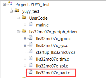
工程需添加库文件lks32mc07x_uart.c
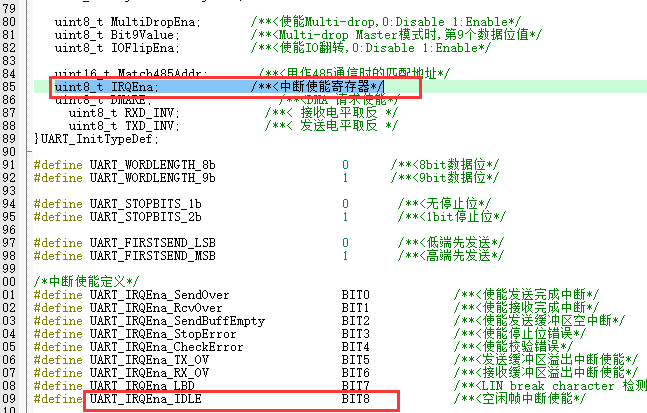
初始化的时候发现初始化UART的结构体中断位是8位的,空闲中断是bit8,也就是没办法通过初始化UART的结构体设置空闲中断
代码示例
- #define UART_BUFF_LEN 16
- uint8_t uart_buff[17];
- uint8_t uart_rxlen = 0;
- void uart_init()
- {
- GPIO_InitTypeDef GPIO_InitStruct;
- GPIO_StructInit(&GPIO_InitStruct);
- GPIO_InitStruct.GPIO_Mode = GPIO_Mode_IN;
- GPIO_InitStruct.GPIO_Pin = GPIO_Pin_15;
- GPIO_Init(GPIO0, &GPIO_InitStruct);
- GPIO_InitStruct.GPIO_Mode = GPIO_Mode_OUT;
- GPIO_InitStruct.GPIO_Pin = GPIO_Pin_0;
- GPIO_Init(GPIO1, &GPIO_InitStruct);
-
- GPIO_PinAFConfig(GPIO0, GPIO_PinSource_15, AF4_UART); //P0.15复用为UART_RX
- GPIO_PinAFConfig(GPIO1, GPIO_PinSource_0, AF4_UART); //P1.0复用为UART_TX
-
- UART_InitTypeDef UART_InitStruct;
-
- UART_StructInit(&UART_InitStruct);
- UART_InitStruct.BaudRate = 115200; /* 设置波特率115200 */
- UART_InitStruct.WordLength = UART_WORDLENGTH_8b; /* 发送数据长度8位 */
- UART_InitStruct.StopBits = UART_STOPBITS_1b; /* 停止位1位 */
- UART_InitStruct.FirstSend = UART_FIRSTSEND_LSB; /* 先发送LSB */
- UART_InitStruct.ParityMode = UART_Parity_NO; /* 无奇偶校验 */
- //UART_InitStruct.IRQEna = UART_IRQEna_RcvOver|UART_IRQEna_IDLE; /* 空闲中断还不能这么设置 */
- UART_Init(UART0, &UART_InitStruct);
- UART0->IE = UART_IRQEna_RcvOver|UART_IRQEna_IDLE;//接收中断和空闲中断
-
- NVIC_EnableIRQ(UART0_IRQn); /* 使能UART_IRQn外部中断*/
- NVIC_SetPriority(UART0_IRQn, 0); /* UART_IRQn外部中断优先级设置为0*/
- }
- void UART0_IRQHandler(void)
- {
- if (UART_GetIRQFlag(UART0, UART_IF_RcvOver)) // 接收完成中断
- {
- UART_ClearIRQFlag(UART0, UART_IF_RcvOver); // 清除接收完成标志位
- uart_buff[uart_rxlen] = UART_ReadData(UART0); // 接收 1 Byte数据
- uart_rxlen++;
- }
- if (UART_GetIRQFlag(UART0, UART_IF_IDLE) || uart_rxlen == UART_BUFF_LEN) // 空闲中断
- {
- UART_ClearIRQFlag(UART0, UART_IF_IDLE); // 清除空闲标志位
- while(uart_rxlen < UART_BUFF_LEN)
- {
- uart_buff[uart_rxlen] = ' ';
- uart_rxlen++;
- }
- uart_buff[UART_BUFF_LEN] = '\0';
- yuyy_hs12864g18b_display_string_8x16(0,6,0,uart_buff);
- yuyy_hs12864g18b_display_finish();
- uart_rxlen = 0;
- }
- }
- void mcu_init(void)
- {
- __disable_irq(); /* 关闭中断 中断总开关 */
- SYS_WR_PROTECT = 0x7a83; /*使能系统寄存器写操作*/
- FLASH_CFG |= 0x00080000; /* enable prefetch ,FLASH预取加速使能*/
- IWDG_DISABLE(); /*关闭清零看门狗*/
- SYS_MclkChoice(SYS_MCLK_96M_RC); /*选择当前主时钟频率*/
- yuyy_hs12864g18b_init();
- uart_init();
- yuyy_delay_us(100); /* 延时等待硬件初始化稳定 */
- SYS_WR_PROTECT = 0x0; /*关闭系统寄存器写操作*/
- __enable_irq(); /* 开启总中断 */
- }
- int main(void)
- {
- mcu_init();
- yuyy_hs12864g18b_clear_screen();
- yuyy_hs12864g18b_display_string_8x16(0,0,0,(uint8_t *)"LKS32MC071 SPI");
- yuyy_hs12864g18b_display_string_8x16(0,2,0,(uint8_t *)"12864LCD TEST");
- yuyy_hs12864g18b_display_string_8x16(0,4,0,(uint8_t *)"Code by yuyy1989");
- yuyy_hs12864g18b_display_finish();
- while (1)
- {
- }
- }

4.5 ADC电位器
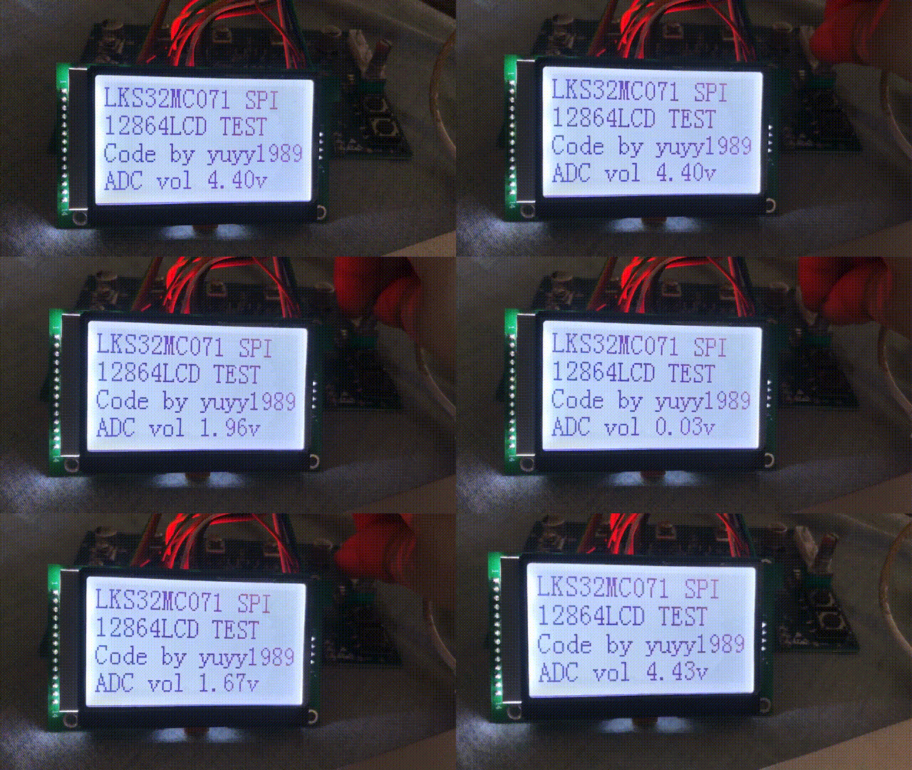
底板上有个可调电位器,用它来测试一下ADC功能,将电位器调节后的电压用串口和LCD屏显示出来
工程需添加库文件lks32mc07x_adc.c和lks32mc07x_nvr.lib

代码示例
- void adc_init()
- {
- ADC_InitTypeDef ADC_InitStructure;
-
- ADC_StructInit(&ADC_InitStructure);
- //ADC_InitStructure.IE = ADC_SF1_IE | ADC_SF2_IE; // 中断使能
- ADC_InitStructure.RE = 0; // DMA请求使能
- ADC_InitStructure.NSMP = DISABLE; // 两段采样使能
- ADC_InitStructure.DATA_ALIGN = DISABLE; // 禁用DAT右对齐使能
- ADC_InitStructure.CSMP = DISABLE; // 连续采样使能
- ADC_InitStructure.TCNT = 1; // 触发一次采样所需的事件数
- ADC_InitStructure.TROVS = ENABLE; // 手动触发过采样使能,开启后一次采样需要多次触发
- ADC_InitStructure.OVSR = 0; // 过采样率
- ADC_InitStructure.S1 = 4; // 第一段常规采样次数
- ADC_InitStructure.S2 = 0; // 第二段常规采样次数
- ADC_InitStructure.IS1 = 0; // 空闲采样次数
- ADC_InitStructure.LTH = 0; // ADC 模拟看门狗 0 下阈值
- ADC_InitStructure.HTH = 0; // ADC 模拟看门狗 0 上阈值
- ADC_InitStructure.GEN = 0; // ADC 模拟看门狗 0 对应使能位
- ADC_Init(ADC0, &ADC_InitStructure);
- ADC_ClearIRQFlag(ADC0, ADC_ALL_IF);//清除所有中断标志位
-
- ADC_CHN_GAIN_CFG(ADC0,CHN0,ADC_CHANNEL_9,ADC_GAIN3V6);
- ADC_CHN_GAIN_CFG(ADC0,CHN1,ADC_CHANNEL_9,ADC_GAIN3V6);
- ADC_CHN_GAIN_CFG(ADC0,CHN2,ADC_CHANNEL_9,ADC_GAIN3V6);
- ADC_CHN_GAIN_CFG(ADC0,CHN3,ADC_CHANNEL_9,ADC_GAIN3V6);
- }
- void mcu_init(void)
- {
- __disable_irq(); /* 关闭中断 中断总开关 */
- SYS_WR_PROTECT = 0x7a83; /*使能系统寄存器写操作*/
- FLASH_CFG |= 0x00080000; /* enable prefetch ,FLASH预取加速使能*/
- IWDG_DISABLE(); /*关闭清零看门狗*/
- SYS_MclkChoice(SYS_MCLK_96M_RC); /*选择当前主时钟频率*/
- led_init();
- yuyy_hs12864g18b_init();
- uart_init();
- adc_init();
- yuyy_delay_us(100); /* 延时等待硬件初始化稳定 */
- SYS_WR_PROTECT = 0x0; /*关闭系统寄存器写操作*/
- __enable_irq(); /* 开启总中断 */
- }
- int main(void)
- {
- int32_t adcval = 0;
- float vol = 0;
- uint8_t lcdout[17] = {0};
- mcu_init();
- yuyy_hs12864g18b_clear_screen();
- yuyy_hs12864g18b_display_string_8x16(0,0,0,(uint8_t *)"LKS32MC071 SPI");
- yuyy_hs12864g18b_display_string_8x16(0,2,0,(uint8_t *)"12864LCD TEST");
- yuyy_hs12864g18b_display_string_8x16(0,4,0,(uint8_t *)"Code by yuyy1989");
- yuyy_hs12864g18b_display_finish();
- while (1)
- {
- yuyy_delay_ms(500);
- ADC_SoftTrgEN(ADC0,ENABLE);
- //while(!ADC_GetIRQFlag(ADC0,ADC_SF1_IF));
- adcval = ADC_GetConversionValue(ADC0,DAT0) + ADC_GetConversionValue(ADC0,DAT1) + ADC_GetConversionValue(ADC0,DAT2)+ADC_GetConversionValue(ADC0,DAT3);
- adcval /= 64; //右移4位相当于/16,再取平均数/4
- vol = (float)adcval/2047 *3.6 / 2 * 3; //反推ZB点电压值
- printf("ADC %d %d %d %d\r\n",ADC_GetConversionValue(ADC0,DAT0),ADC_GetConversionValue(ADC0,DAT1),ADC_GetConversionValue(ADC0,DAT2),ADC_GetConversionValue(ADC0,DAT3));
- printf("ADC vol %.2fv",vol);
- sprintf((char *)lcdout,"ADC vol %.2fv",vol);
- yuyy_hs12864g18b_display_string_8x16(0,6,0,lcdout);
- }
- }
