本帖最后由 BinWin 于 2018-2-25 21:06 编辑
感谢二姨送出的萤火虫,不仅有了ESP32,俨然也是一个arduino开发板,首次入手,对比了一下开发环境,首先以arduino切入。
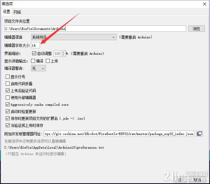
下载windows平台的安装包,安装过程就不需多说了。第一次打开后,字体较小,并且比较难看,费眼睛,找了半天,修改方式如下

这里只能更改字体大小,修改配置文件来更改使用的字体。这个字体路径在用户下的AppData中,要查看隐藏文件
![DB2J6]6AE%]N{EX8~WQ$}FT.png DB2J6]6AE%]N{EX8~WQ$}FT.png](/data/attachment/forum/201802/25/202419kjyqy5mjj15u2n4r.png)
打开这个文件可以修改很多内容,不过要先关闭IDE,重新打开就可以生效了
- board=firebeetle32
- boardsmanager.additional.urls=
- build.verbose=false
- build.warn_data_percentage=75
- compiler.cache_core=true
- compiler.warning_level=none
- console=true
- console.auto_clear=true
- console.error.file=stderr.txt
- console.length=500
- console.lines=4
- console.output.file=stdout.txt
- custom_FlashFreq=firebeetle32_80
- custom_UploadSpeed=firebeetle32_921600
- editor.antialias=true
- editor.auto_close_braces=true
- editor.caret.blink=true
- editor.code_folding=false
- editor.divider.size=2
- editor.external=false
- editor.font=Microsoft YaHei Mono,plain,14
- editor.indent=true
- .........
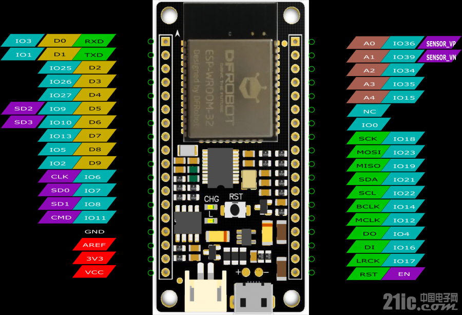
来看下板子的资源

小板子上有两个LED,可以使用的LED对应的口线是D9,于是点灯的程序就可以这样
- void setup() {
- // initialize digital pin LED_BUILTIN as an output.
- pinMode(LED_BUILTIN, OUTPUT);
- }
- // the loop function runs over and over again forever
- void loop() {
- digitalWrite(LED_BUILTIN, HIGH); // turn the LED on (HIGH is the voltage level)
- delay(1000); // wait for a second
- digitalWrite(LED_BUILTIN, LOW); // turn the LED off by making the voltage LOW
- delay(1000); // wait for a second
- }

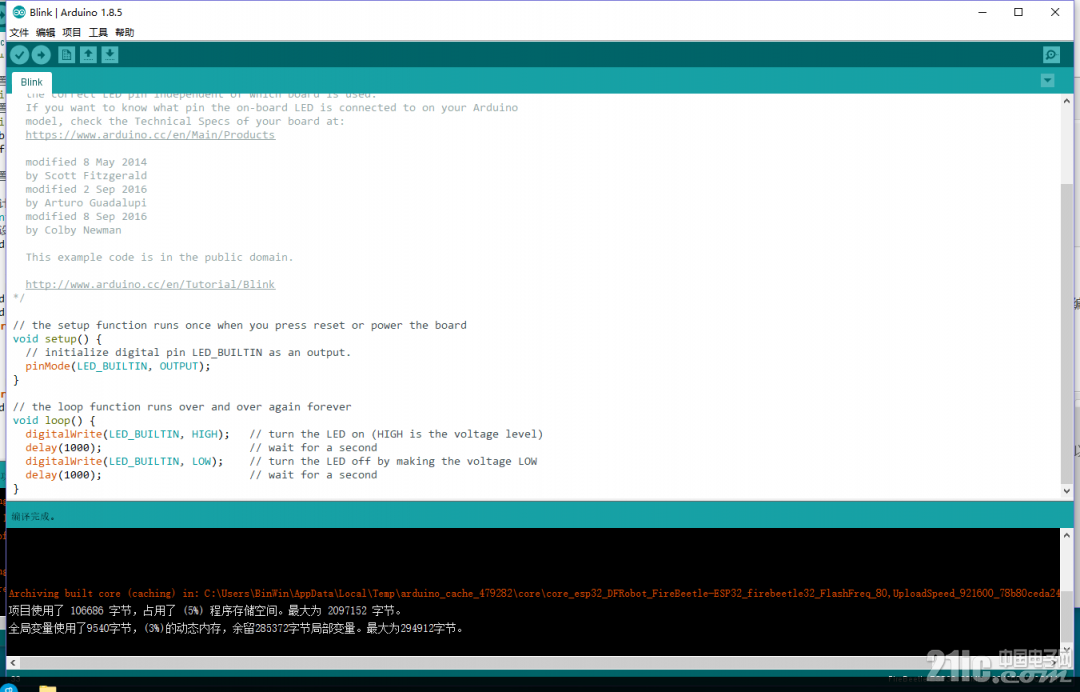
直接点击上传会先进行编译后再上传,对于esp32来说,代码是存放在外部16M的flash中的,和通常使用的单片机有所不同,这里对flash编程算法部分不做详细说明。上传成功可以看到蓝色的led已1秒频率闪烁。
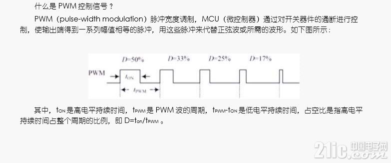
以上可以验证成功的操作了IO口。只有一个led,那再尝试一下呼吸灯。对照dfrobot给出的用户手册来看下PWM的定义

然后在通过arduino高度封装的代码来配置一个脉冲输出
- //设置通道 0
- #define LEDC_CHANNEL_0 0
-
- //设置 13 位定时器
- #define LEDC_TIMER_13_BIT 13
-
- //设置定时器频率位 5000Hz
- #define LEDC_BASE_FREQ 5000
- //设置 LED 灯
- #define LED_PIN D9
- int brightness = 0; // how bright the LED is
- int fadeAmount = 5; // how many points to fade the LED by
-
- //设置 led 灯的亮度
- void ledcAnalogWrite(uint32_t value, uint32_t valueMax = 255) {
- //计算占空比
- uint32_t duty = (LEDC_BASE_FREQ / valueMax) * min(value, valueMax);
- //设置占空比
- ledcWrite(LEDC_CHANNEL_0, duty);
- }
- void setup() {
- // put your setup code here, to run once:
- ledcSetup(LEDC_CHANNEL_0, LEDC_BASE_FREQ, LEDC_TIMER_13_BIT);
- ledcAttachPin(LED_PIN, LEDC_CHANNEL_0);
- }
- void loop() {
- // put your main code here, to run repeatedly:
- ledcAnalogWrite(brightness); brightness += fadeAmount;
-
- if (brightness <= 0 || brightness >= 255) { fadeAmount = -fadeAmount; } delay(30);
- }
|