开发板:LP-MSPM0L1306 LaunchPad
例程说明:通过短接TX和RX的引脚,让TX的数据直接发送到RX引脚上,来实现串口发送和接收的例程。使用FIFO的方式实现串口的发送和接收。如果发送和接收都完成,用户LED会闪烁,如果发送和接收没完成,用户LED常亮。
开发板的操作:需要断开J101上TXD和RXD与XDS110-ET下载板的连接,短接TXD与RXD。
例程分析:
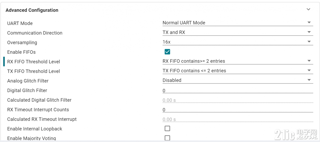
1、首先是串口的配置,波特率照常配置,只需要使能FIFO,以及配置发送和接收FIFO的长度即可

2、代码如下所示:
- #include "ti_msp_dl_config.h"
- /*
- * Configure the internal loopback mode.
- * Note that data received on the UART RXD IO pin will be ignored when
- * loopback is enabled.
- */
- #define ENABLE_LOOPBACK_MODE true
- /*
- * Number of bytes for UART packet size
- * The packet will be transmitted by the UART.
- * This example uses FIFOs with polling, and the maximum FIFO size is 4.
- * Refer to interrupt examples to handle larger packets.
- */
- #define UART_PACKET_SIZE (4)
- /* Delay for 5ms to ensure UART TX is idle before starting transmission */
- #define UART_TX_DELAY (160000)
- /* Data for UART to transmit */
- uint8_t txPacket[UART_PACKET_SIZE] = {'M', 'S', 'P', '!'};
- /* Data received from UART */
- uint8_t rxPacket[UART_PACKET_SIZE];
- int main(void)
- {
- SYSCFG_DL_init();//系统初始化
- /* Optional delay to ensure UART TX is idle before starting transmission */
- delay_cycles(UART_TX_DELAY);
- /* Set LED to indicate start of transfer */
- DL_GPIO_clearPins(GPIO_LEDS_PORT, GPIO_LEDS_USER_LED_1_PIN);
- /* Fills TX FIFO with data and transmits the data */
- DL_UART_Main_fillTXFIFO(UART_0_INST, &txPacket[0], UART_PACKET_SIZE);//填充数据发送数组并发送数据
- /* Wait until all bytes have been transmitted and the TX FIFO is empty */
- while (DL_UART_Main_isBusy(UART_0_INST))//等待数据发送完毕
- ;
- /*
- * Wait to receive the UART data
- * This loop expects UART_PACKET_SIZE bytes
- */
- for (uint8_t i = 0; i < UART_PACKET_SIZE; i++) {
- rxPacket[i] = DL_UART_receiveDataBlocking(UART_0_INST);
- }//循环接收发送的数据到接收缓存区,因为TX和RX对接了
- /* If write and read were successful, toggle LED */
- //假如发送和接收成功的话,才会进去下面的while循环
- while (1) {
- DL_GPIO_togglePins(GPIO_LEDS_PORT,
- GPIO_LEDS_USER_LED_1_PIN | GPIO_LEDS_USER_TEST_PIN);
- delay_cycles(5000000);
- }
- }
|