[APM32E0] APM32E030R Mirco-EVB开发板驱动flash

[复制链接]
 楼主| sujingliang 发表于 2025-6-6 10:32 | 显示全部楼层 |阅读模式
本帖最后由 sujingliang 于 2025-6-6 10:33 编辑

很荣幸在《@开发者们!100+开发板免费领,上海慕尼黑 电子展见》活动中获得一个块APM32E030R开发板。

此次,我首次通过回帖的方式收获幸运,这究竟是幸运之神偶然的恩赐,还是我本就是幸运之子,此刻不过是命运轨迹中一次恰到好处的回归?
不管怎样,感谢极海半导体,感谢21IC。

下面是APM32E030R开发板:

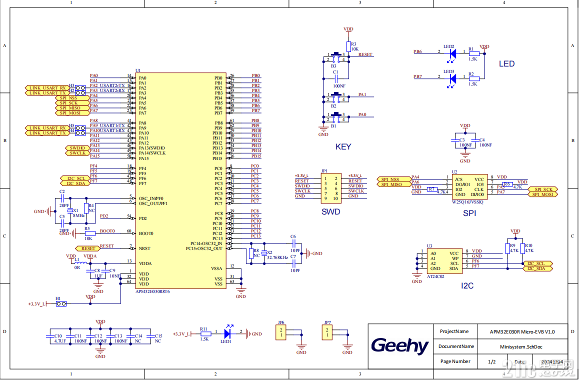
原理图:
1.png

可以看到原理图上留有FLASH的扩展(开发板上这部分没有焊接)。

所以我在开发板上补上了一个W25Q80并进行了驱动
1.jpg

1、SPI初始化
对时钟、引脚、SPI等进行初始化
3.png
  1. void SPI_InitForFlash(void)
  2. {
  3.     SPI_Config_T spiConfig;
  4.     GPIO_Config_T gpioConfig;
  5.    
  6.     // 使能时钟
  7.     RCM_EnableAPB2PeriphClock(RCM_APB2_PERIPH_SPI1);
  8.     RCM_EnableAHBPeriphClock(RCM_AHB_PERIPH_GPIOA);
  9.    
  10.     RCM_EnableAPB2PeriphClock(RCM_APB2_PERIPH_SYSCFG);
  11.         
  12.         
  13.             /* Config alter function*/
  14.     GPIO_ConfigPinAF(GPIOA, GPIO_PIN_SOURCE_5, GPIO_AF_PIN0);
  15.     GPIO_ConfigPinAF(GPIOA, GPIO_PIN_SOURCE_6, GPIO_AF_PIN0);
  16.     GPIO_ConfigPinAF(GPIOA, GPIO_PIN_SOURCE_7, GPIO_AF_PIN0);
  17.         
  18.     // 配置SPI引脚
  19.     // PA5 - SCK, PA6 - MISO, PA7 - MOSI
  20.     gpioConfig.pin = GPIO_PIN_5 | GPIO_PIN_7;
  21.     gpioConfig.mode = GPIO_MODE_AF;
  22.     gpioConfig.speed = GPIO_SPEED_50MHz;
  23.     gpioConfig.outtype = GPIO_OUT_TYPE_PP;
  24.     gpioConfig.pupd = GPIO_PUPD_PU;
  25.     GPIO_Config(GPIOA, &gpioConfig);
  26.    
  27.     // 配置CS引脚(假设使用PA4)
  28.     gpioConfig.pin = GPIO_PIN_4;
  29.     gpioConfig.outtype = GPIO_OUT_TYPE_PP;
  30.                 gpioConfig.speed = GPIO_SPEED_50MHz;
  31.     gpioConfig.pupd = GPIO_PUPD_PU;
  32.     gpioConfig.mode = GPIO_MODE_OUT;
  33.     GPIO_Config(GPIOA, &gpioConfig);
  34.     GPIO_SetBit(GPIOA, GPIO_PIN_4); // 初始高电平(不选中)
  35.                
  36.                 /* config PIN_6  MISO*/
  37.     gpioConfig.pin = GPIO_PIN_6;
  38.     gpioConfig.mode = GPIO_MODE_AF;
  39.     gpioConfig.pupd = GPIO_PUPD_PU;
  40.     gpioConfig.speed = GPIO_SPEED_50MHz;
  41.     GPIO_Config(GPIOA, &gpioConfig);
  42.                
  43.    
  44.      /* SPI RESET*/
  45.     SPI_Reset(SPI1);
  46.     SPI_ConfigStructInit(&spiConfig);

  47.     /* SPI configuration*/
  48.     /* Set Clock polarity is Low, but Slave is High*/
  49.     spiConfig.polarity = SPI_CLKPOL_LOW;

  50.     /* select master mode*/
  51.     spiConfig.mode = SPI_MODE_MASTER;

  52.     /* SPI Clock Phase is 1EDGE, but Slave is 1EDGE*/
  53.     spiConfig.phase = SPI_CLKPHA_1EDGE;

  54.     /* Enable Software slave control */
  55.     spiConfig.slaveSelect = SPI_SSC_ENABLE;

  56.     /* Set SPI BaudRate divider*/
  57.     spiConfig.baudrateDiv = SPI_BAUDRATE_DIV_256;

  58.     /* SPI data length*/
  59.     spiConfig.length = SPI_DATA_LENGTH_8B;

  60.     /* Set internal slave*/
  61.     SPI_EnableInternalSlave(SPI1);
  62.     SPI_Config(SPI1, &spiConfig);
  63.     SPI_ConfigFIFOThreshold(SPI1, SPI_RXFIFO_QUARTER);

  64.     SPI_Enable(SPI1);
  65. }


2、片选控制
  1. // 片选控制
  2. static void FLASH_CS_Low(void) {
  3.     GPIO_ClearBit(GPIOA, GPIO_PIN_4);
  4. }

  5. static void FLASH_CS_High(void) {
  6.     GPIO_SetBit(GPIOA, GPIO_PIN_4);
  7. }


3、发送单字节
  1. // SPI发送接收单字节
  2. static uint8_t SPI_TransmitReceiveByte(uint8_t data)
  3. {
  4.     while(SPI_ReadStatusFlag(SPI1, SPI_FLAG_TXBE) == RESET);
  5.     SPI_TxData8(SPI1, data);
  6.    
  7.     while(SPI_ReadStatusFlag(SPI1, SPI_FLAG_RXBNE) == RESET);
  8.     return SPI_RxData8(SPI1);
  9. }


4、写使能
  1. static void FLASH_WriteEnable(void)
  2. {
  3.     FLASH_CS_Low();
  4.     SPI_TransmitReceiveByte(0x06); // 写使能命令
  5.     FLASH_CS_High();
  6. }


5、读取数据
  1. void FLASH_ReadData(uint32_t addr, uint8_t *pData, uint32_t size)
  2. {
  3.     FLASH_CS_Low();
  4.     SPI_TransmitReceiveByte(0x03); // 读数据命令
  5.    
  6.     // 发送地址(24位)
  7.     SPI_TransmitReceiveByte((addr >> 16) & 0xFF);
  8.     SPI_TransmitReceiveByte((addr >> 8) & 0xFF);
  9.     SPI_TransmitReceiveByte(addr & 0xFF);
  10.    
  11.     // 读取数据
  12.     while(size--) {
  13.         *pData++ = SPI_TransmitReceiveByte(0xFF);
  14.     }
  15.    
  16.     FLASH_CS_High();
  17. }
6、页编程(写入数据,通常256字节一页)
  1. void FLASH_PageProgram(uint32_t addr, uint8_t *pData, uint32_t size)
  2. {
  3.     FLASH_WriteEnable();
  4.     FLASH_WaitForReady();
  5.    
  6.     FLASH_CS_Low();
  7.     SPI_TransmitReceiveByte(0x02); // 页编程命令
  8.    
  9.     // 发送地址
  10.     SPI_TransmitReceiveByte((addr >> 16) & 0xFF);
  11.     SPI_TransmitReceiveByte((addr >> 8) & 0xFF);
  12.     SPI_TransmitReceiveByte(addr & 0xFF);
  13.    
  14.     // 写入数据
  15.     while(size--) {
  16.         SPI_TransmitReceiveByte(*pData++);
  17.     }
  18.    
  19.     FLASH_CS_High();
  20.     FLASH_WaitForReady(); // 等待写入完成
  21. }
7、扇区擦除(通常4KB)
  1. void FLASH_SectorErase(uint32_t addr)
  2. {
  3.     FLASH_WriteEnable();
  4.     FLASH_WaitForReady();
  5.    
  6.     FLASH_CS_Low();
  7.     SPI_TransmitReceiveByte(0x20); // 扇区擦除命令
  8.    
  9.     // 发送地址
  10.     SPI_TransmitReceiveByte((addr >> 16) & 0xFF);
  11.     SPI_TransmitReceiveByte((addr >> 8) & 0xFF);
  12.     SPI_TransmitReceiveByte(addr & 0xFF);
  13.    
  14.     FLASH_CS_High();
  15.     FLASH_WaitForReady(); // 等待擦除完成
  16. }
8、等待FLASH就绪
  1. static void FLASH_WaitForReady(void)
  2. {
  3.     uint8_t status;
  4.    
  5.     FLASH_CS_Low();
  6.     SPI_TransmitReceiveByte(0x05); // 读状态寄存器命令
  7.    
  8.     do {
  9.         status = SPI_TransmitReceiveByte(0xFF);
  10.     } while(status & 0x01); // 检查BUSY位
  11.    
  12.     FLASH_CS_High();
  13. }
9、读取FLASH ID (用于测试通信)
  1. uint32_t FLASH_ReadID(void)
  2. {
  3.     uint32_t id = 0;
  4.    
  5.     FLASH_CS_Low();
  6.     SPI_TransmitReceiveByte(0x9F); // 读ID命令
  7.    
  8.     id |= (SPI_TransmitReceiveByte(0xFF) << 16);
  9.     id |= (SPI_TransmitReceiveByte(0xFF) << 8);
  10.     id |= SPI_TransmitReceiveByte(0xFF);
  11.    
  12.     FLASH_CS_High();
  13.     return id;
  14. }
10、flash测试程序
  1. void flash_test(void)
  2. {
  3.     uint8_t readBuffer[256];
  4.     uint8_t writeBuffer[256];
  5.     uint32_t flashID;
  6.         
  7.   // 读取FLASH ID
  8.     flashID = FLASH_ReadID();
  9.     printf("FLASH ID: 0x%06lX\n", (unsigned long)flashID);
  10.         
  11. // 准备测试数据
  12.     for(int i = 0; i < 256; i++) {
  13.         writeBuffer[i] = i;
  14.     }
  15.    
  16.     // 擦除扇区(假设擦除地址0x000000)
  17.     FLASH_SectorErase(0x000000);
  18.    
  19.     // 写入数据
  20.     FLASH_PageProgram(0x000000, writeBuffer, 256);
  21.    
  22.     // 读取验证
  23.     FLASH_ReadData(0x000000, readBuffer, 256);        
  24.                
  25.                 for(int i = 0; i < 256; i++) {
  26.                         printf("0x%02X ",readBuffer[i] );
  27.     }
  28. }

11、main函数
  1. int main(void)
  2. {
  3.                 APM_TINY_COMInit(COM1);
  4.                 // 初始化
  5.     SPI_InitForFlash();
  6.         
  7.                 printf("Flash demo program start\r\n");
  8.         
  9.                 flash_test();
  10.     while (1)
  11.     {
  12.     }
  13. }
12、运行
可以看到已经读取到FLASH ID,并且读写测试输出符合预期
2.png


FrostShimmer 发表于 2025-7-3 19:36 | 显示全部楼层
楼主真棒!
好棒的技术分享
话说楼主的焊功厉害,焊完了,器件周围还是这么干净
pacer81 发表于 2025-7-4 05:18 | 显示全部楼层
这款产品SPI最高速率是18MHz,不知道有没有达到?另外18MHz是不是有点低了
Gfan 发表于 2025-7-4 10:00 | 显示全部楼层
本帖最后由 Gfan 于 2025-7-4 10:03 编辑
pacer81 发表于 2025-7-4 05:18
这款产品SPI最高速率是18MHz,不知道有没有达到?另外18MHz是不是有点低了

主要还是看应用,APM32E030R所属的入门级、低成本Cortex-M0+微控制器领域,18MHz的SPI速率处于一个中等甚至偏上的水平。许多同类产品的SPI速率在几MHz到十几MHz之间。而且18MHz的SPI速率对于E030的目标应用领域(工业控制、消费电子、物联网节点等)来说并不算低,甚至可以说是一个不错的性能指标。它在性能和成本之间取得了很好的平衡。只有在与高端MCU或对数据传输率有极端要求的特定应用对比时,这个速率才会显得“低”的。

评论

@pacer81 :对的~这款开发板目前也在开放免费申请活动噢,有兴趣可以了解一下 https://bbs.21ic.com/icview-3461474-1-1.html  发表于 2025-7-4 11:26
明白了,性价比看起来不错,和主频应该也有些关系  发表于 2025-7-4 11:06
天鹅绒之夜 发表于 2025-7-4 20:50 | 显示全部楼层
18MHz的SPI速率相当于4分频主频。
如果不使用DMA,是不是也跑不出来这个速率啊!
银河漫步 发表于 2025-7-5 20:49 | 显示全部楼层
SPI在使用的时候只支持8位模式吗?
您需要登录后才可以回帖 登录 | 注册

本版积分规则

84

主题

146

帖子

3

粉丝
快速回复 在线客服 返回列表 返回顶部