本帖最后由 hbzjt2011 于 2025-8-2 14:11 编辑
1. 概述 本文将介绍如何在Geehy APM32F402R Micro-EVB开发板上,基于RT-Thread实时操作系统和Freemodbus开源库实现Modbus主机功能,并使用Modbus Slave工具进行通信测试。
1.1 硬件平台- 开发板: Geehy APM32F402R Micro-EVB
- MCU: APM32F402RBT6 (Cortex-M4F, 128KB Flash, 32KB SRAM)
- 通信接口: UART2
1.2 软件环境- 操作系统: RT-Thread 5.2.1
- Modbus库: Freemodbus 1.6
- 开发环境: Keil MDK
- 测试工具: Modbus Slave
1.3 FreeModbus 简介FreeModbus 是一个基于 BSD 协议的开源嵌入式 Modbus 协议栈,支持 RTU、ASCII 及 TCP 三种传输模式,具有高度可移植性和模块化设计。它可运行于裸机系统,也适用于集成 RTOS 的嵌入式平台,特别适合 STM32、AVR、ARM Cortex-M 等微控制器平台。FreeModbus 提供从站和主站功能接口,便于快速集成至工业控制、自动化设备中。我们将采用 RTU 从站模式与主机进行通信,结合 UART 作为物理接口。 标准Modbus功能: - 支持保持寄存器读写(功能码03/06/16)
- 支持输入寄存器读取(功能码04)
- 支持线圈读写(功能码01/05/15)
- 支持离散输入读取(功能码02)
系统架构
- 应用层 (user_mb_app.c)
- ↓
- Modbus协议栈 (mb.c, mbrtu.c等)
- ↓
- 移植层 (mb_port_*.c)
- ↓
- ThreadX RTOS
- ↓
- APM32F402硬件层
2. 环境搭建2.1 RT-Thread配置在RT-Thread配置中启用以下组件:
- RT-Thread Components → Device Drivers → Using Serial Device Drivers
- RT-Thread Components → Device Drivers → Using Pin Device Drivers
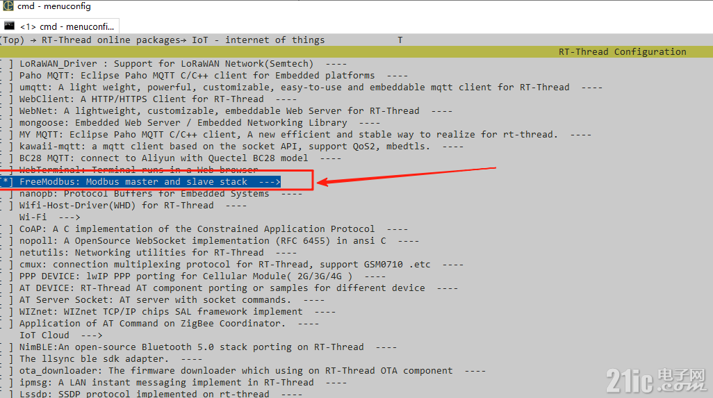
- RT-Thread online packages → IoT - internet of things → freemodbus


2.2 Freemodbus软件包配置在RT-Thread配置菜单中设置: 使用pkgs --update更新组件 使用scons --target=mdk5更新工程
3. 软件实现
生成的Keil工程如下:

board.c
- /*
- * Copyright (c) 2006-2022, RT-Thread Development Team
- *
- * SPDX-License-Identifier: Apache-2.0
- *
- * Change Logs:
- * Date Author Notes
- * 2020-08-20 Abbcc first version
- */
- #include "board.h"
- void apm32_usart_init(void)
- {
- GPIO_Config_T GPIO_ConfigStruct = {0U};
- #ifdef BSP_USING_UART1
- RCM_EnableAPB2PeriphClock(RCM_APB2_PERIPH_GPIOA);
- RCM_EnableAPB2PeriphClock(RCM_APB2_PERIPH_USART1);
- GPIO_ConfigStruct.mode = GPIO_MODE_AF_PP;
- GPIO_ConfigStruct.pin = GPIO_PIN_9;
- GPIO_ConfigStruct.speed = GPIO_SPEED_50MHz;
- GPIO_Config(GPIOA, &GPIO_ConfigStruct);
- GPIO_ConfigStruct.mode = GPIO_MODE_IN_FLOATING;
- GPIO_ConfigStruct.pin = GPIO_PIN_10;
- GPIO_ConfigStruct.speed = GPIO_SPEED_50MHz;
- GPIO_Config(GPIOA, &GPIO_ConfigStruct);
- #endif
- #ifdef BSP_USING_UART2
- RCM_EnableAPB2PeriphClock(RCM_APB2_PERIPH_GPIOA);
- RCM_EnableAPB1PeriphClock(RCM_APB1_PERIPH_USART2);
- GPIO_ConfigStruct.mode = GPIO_MODE_AF_PP;
- GPIO_ConfigStruct.pin = GPIO_PIN_2;
- GPIO_ConfigStruct.speed = GPIO_SPEED_50MHz;
- GPIO_Config(GPIOA, &GPIO_ConfigStruct);
- GPIO_ConfigStruct.mode = GPIO_MODE_IN_FLOATING;
- GPIO_ConfigStruct.pin = GPIO_PIN_3;
- GPIO_ConfigStruct.speed = GPIO_SPEED_50MHz;
- GPIO_Config(GPIOA, &GPIO_ConfigStruct);
- #endif
- }
- void apm32_msp_can_init(void *Instance)
- {
- #if defined(BSP_USING_CAN1) || defined(BSP_USING_CAN2)
- GPIO_Config_T GPIO_InitStructure;
- CAN_T *CANx = (CAN_T *)Instance;
- if (CAN1 == CANx)
- {
- RCM_EnableAPB1PeriphClock(RCM_APB1_PERIPH_CAN1);
- RCM_EnableAHB1PeriphClock(RCM_AHB1_PERIPH_GPIOB);
- /* PB8: CAN1_RX, PB9: CAN1_TX */
- GPIO_InitStructure.pin = GPIO_PIN_8 | GPIO_PIN_9;
- GPIO_InitStructure.mode = GPIO_MODE_AF;
- GPIO_InitStructure.otype = GPIO_OTYPE_PP;
- GPIO_InitStructure.speed = GPIO_SPEED_100MHz;
- GPIO_InitStructure.pupd = GPIO_PUPD_UP;
- GPIO_Config(GPIOB, &GPIO_InitStructure);
- GPIO_ConfigPinAF(GPIOB, GPIO_PIN_SOURCE_8, GPIO_AF_CAN1);
- GPIO_ConfigPinAF(GPIOB, GPIO_PIN_SOURCE_9, GPIO_AF_CAN1);
- }
- else if (CAN2 == CANx)
- {
- /* When using the CAN2 peripheral, the CAN1 clock must be turned on */
- RCM_EnableAPB1PeriphClock(RCM_APB1_PERIPH_CAN1);
- RCM_EnableAPB1PeriphClock(RCM_APB1_PERIPH_CAN2);
- RCM_EnableAHB1PeriphClock(RCM_AHB1_PERIPH_GPIOB);
- /* PB12: CAN2_RX, PB13: CAN2_TX */
- GPIO_InitStructure.pin = GPIO_PIN_12 | GPIO_PIN_13;
- GPIO_InitStructure.mode = GPIO_MODE_AF;
- GPIO_InitStructure.otype = GPIO_OTYPE_PP;
- GPIO_InitStructure.speed = GPIO_SPEED_100MHz;
- GPIO_InitStructure.pupd = GPIO_PUPD_UP;
- GPIO_Config(GPIOB, &GPIO_InitStructure);
- GPIO_ConfigPinAF(GPIOB, GPIO_PIN_SOURCE_12, GPIO_AF_CAN2);
- GPIO_ConfigPinAF(GPIOB, GPIO_PIN_SOURCE_13, GPIO_AF_CAN2);
- }
- #endif
- }
- /*
- * Copyright (c) 2006-2022, RT-Thread Development Team
- *
- * SPDX-License-Identifier: Apache-2.0
- *
- * Change Logs:
- * Date Author Notes
- * 2019-06-21 flybreak first version
- */
- #include <rtthread.h>
- #include "mb.h"
- #include "mb_m.h"
- #ifdef PKG_MODBUS_MASTER_SAMPLE
- #define SLAVE_ADDR MB_SAMPLE_TEST_SLAVE_ADDR
- #define PORT_NUM MB_MASTER_USING_PORT_NUM
- #define PORT_BAUDRATE MB_MASTER_USING_PORT_BAUDRATE
- #else
- #define SLAVE_ADDR 0x01
- #define PORT_NUM 3
- #define PORT_BAUDRATE 115200
- #endif
- #define PORT_PARITY MB_PAR_EVEN
- #define MB_POLL_THREAD_PRIORITY 10
- #define MB_SEND_THREAD_PRIORITY RT_THREAD_PRIORITY_MAX - 1
- #define MB_SEND_REG_START 2
- #define MB_SEND_REG_NUM 2
- #define MB_POLL_CYCLE_MS 500
- static void send_thread_entry(void *parameter)
- {
- eMBMasterReqErrCode error_code = MB_MRE_NO_ERR;
- rt_uint16_t error_count = 0;
- USHORT data[MB_SEND_REG_NUM] = {0};
- while (1)
- {
- /* Test Modbus Master */
- data[0] = (USHORT)(rt_tick_get() / 10);
- data[1] = (USHORT)(rt_tick_get() % 10);
- error_code = eMBMasterReqWriteMultipleHoldingRegister(SLAVE_ADDR, /* salve address */
- MB_SEND_REG_START, /* register start address */
- MB_SEND_REG_NUM, /* register total number */
- data, /* data to be written */
- RT_WAITING_FOREVER); /* timeout */
- /* Record the number of errors */
- if (error_code != MB_MRE_NO_ERR)
- {
- error_count++;
- }
- }
- }
- static void mb_master_poll(void *parameter)
- {
- eMBMasterInit(MB_RTU, PORT_NUM, PORT_BAUDRATE, PORT_PARITY);
- eMBMasterEnable();
- while (1)
- {
- eMBMasterPoll();
- rt_thread_mdelay(MB_POLL_CYCLE_MS);
- }
- }
- static int mb_master_sample(int argc, char **argv)
- {
- static rt_uint8_t is_init = 0;
- rt_thread_t tid1 = RT_NULL, tid2 = RT_NULL;
- if (is_init > 0)
- {
- rt_kprintf("sample is running\n");
- return -RT_ERROR;
- }
- tid1 = rt_thread_create("md_m_poll", mb_master_poll, RT_NULL, 512, MB_POLL_THREAD_PRIORITY, 10);
- if (tid1 != RT_NULL)
- {
- rt_thread_startup(tid1);
- }
- else
- {
- goto __exit;
- }
- tid2 = rt_thread_create("md_m_send", send_thread_entry, RT_NULL, 512, MB_SEND_THREAD_PRIORITY - 2, 10);
- if (tid2 != RT_NULL)
- {
- rt_thread_startup(tid2);
- }
- else
- {
- goto __exit;
- }
- is_init = 1;
- return RT_EOK;
- __exit:
- if (tid1)
- rt_thread_delete(tid1);
- if (tid2)
- rt_thread_delete(tid2);
- return -RT_ERROR;
- }
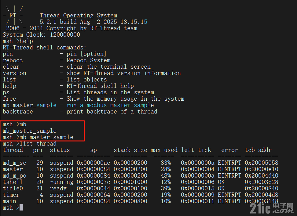
- MSH_CMD_EXPORT(mb_master_sample, run a modbus master sample);

4. 使用Modbus Slave进行测试
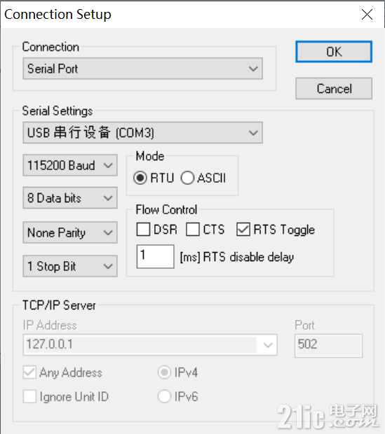
4.1 Modbus Slave设置- 下载并安装Modbus Slave工具
- 配置串口参数:
- 端口:选择对应的COM口
- 波特率:115200
- 数据位:8
- 停止位:1
- 校验位:None
- 从站地址:1

4.2 Modbus Slave测试
可以对保持寄存器进行读取和设置

5. 总结本文介绍了在Geehy APM32F402R Micro-EVB开发板上基于RT-Thread和Freemodbus实现Modbus主机的过程: - 掌握RT-Thread下Freemodbus的配置和使用
- 理解Modbus主机的工作原理和实现方法
- 学会使用Modbus Slave工具进行通信测试
- 具备扩展更多Modbus功能的能力
|