本帖最后由 xyz549040622 于 2020-12-4 23:01 编辑
拿到一个开发板,在使得GPIO点亮LED闪烁成功,证明最小系统OK后,下一步要做的必然是打通USART接口,使得用户可以与开发板进行数据的交互。
MRS软件在自动创建工程后,会自动创建一个Debug的文件夹,里面包含Debug.c和Debug.h,这里面自动使能了USART1的串口功能,并使用了串口阻塞方式发送数据,并重定义了printf函数,使得程序中可以使用printf函数发送数据。
这里为了方便数据的交互,我们需要增加串口接收数据函数,使用阻塞方式发送数据,因此不使用官方的Debug.c中的函数,从而自己编写串口函数usart.c和usart.h。
友情提示,由于板子上国产SP232的影响,串口1TTL的接收是受影响的,必须把SP232拆掉才能使能串口1的接收,或者改为使用串口2、串口3的接收。如下图所示:

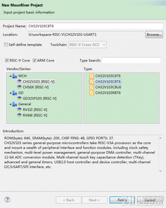
1.在workspace-RISC-V下新建一个文件夹CH32V103C8T6-USART1并将工程命名为CH32V103C8T6-USART1。
 2.删除Debug里的关于串口的全部函数,只保留延时函数,把debug.h变为延时函数。
- /********************************** (C) COPYRIGHT *******************************
- * File Name : debug.c
- * Author : WCH
- * Version : V1.0.0
- * Date : 2020/04/30
- * Description : This file contains all the functions prototypes for UART
- * Printf , Delay functions.
- *******************************************************************************/
- #include "delay.h"
- static uint8_t p_us=0;
- static uint16_t p_ms=0;
- /*******************************************************************************
- * Function Name : Delay_Init
- * Description : Initializes Delay Funcation.
- * Input : None
- * Return : None
- *******************************************************************************/
- void Delay_Init(void)
- {
- p_us=SystemCoreClock/8000000;
- p_ms=(uint16_t)p_us*1000;
- }
- /*******************************************************************************
- * Function Name : Delay_Us
- * Description : Microsecond Delay Time.
- * Input : n:Microsecond number.
- * Return : None
- *******************************************************************************/
- void Delay_Us(uint32_t n)
- {
- uint32_t i;
- SysTick->CTLR = 0;
- i = (uint32_t)n*p_us;
- SysTick->CNTL0 = 0;
- SysTick->CNTL1 = 0;
- SysTick->CNTL2 = 0;
- SysTick->CNTL3 = 0;
- SysTick->CTLR = 1;
- while((*(__IO uint32_t*)0xE000F004) <= i);
- }
- /*******************************************************************************
- * Function Name : Delay_Ms
- * Description : Millisecond Delay Time.
- * Input : n:Millisecond number.
- * Return : None
- *******************************************************************************/
- void Delay_Ms (uint32_t n)
- {
- uint32_t i;
- SysTick->CTLR = 0;
- i = (uint32_t)n*p_ms;
- SysTick->CNTL0 = 0;
- SysTick->CNTL1 = 0;
- SysTick->CNTL2 = 0;
- SysTick->CNTL3 = 0;
- SysTick->CTLR = 1;
- while((*(__IO uint32_t*)0xE000F004) <= i);
- }
3.增加usart.c的串口函数,配置串口1,使能发送和接收功能
- #include "usart.h"
- /*******************************************************************************
- * Function Name : USARTx_CFG
- * Description : Initializes the USART2 peripheral.
- * Input : None
- * Return : None
- *******************************************************************************/
- void USART1_Init(void)
- {
- GPIO_InitTypeDef GPIO_InitStructure;
- USART_InitTypeDef USART_InitStructure;
- NVIC_InitTypeDef NVIC_InitStructure;
- RCC_APB2PeriphClockCmd(RCC_APB2Periph_GPIOA|RCC_APB2Periph_USART1, ENABLE); //使能GPIOA时钟
- USART_DeInit(USART1);
- /* USART2 TX-->A.2 RX-->A.3 */
- GPIO_InitStructure.GPIO_Pin = GPIO_Pin_9;
- GPIO_InitStructure.GPIO_Speed = GPIO_Speed_50MHz;
- GPIO_InitStructure.GPIO_Mode = GPIO_Mode_AF_PP; //设置PA9为复用功能
- GPIO_Init(GPIOA, &GPIO_InitStructure);
- GPIO_InitStructure.GPIO_Pin = GPIO_Pin_10;
- GPIO_InitStructure.GPIO_Mode = GPIO_Mode_IN_FLOATING; //设置PA10为浮空输入
- GPIO_Init(GPIOA, &GPIO_InitStructure);
- USART_InitStructure.USART_BaudRate = 9600; //设置串口波特率为115200
- USART_InitStructure.USART_WordLength = USART_WordLength_8b; //字长为8位数据格式
- USART_InitStructure.USART_StopBits = USART_StopBits_1; //1个停止位
- USART_InitStructure.USART_Parity = USART_Parity_No; //无奇偶校验位
- USART_InitStructure.USART_HardwareFlowControl = USART_HardwareFlowControl_None;//无硬件流控制
- USART_InitStructure.USART_Mode = USART_Mode_Tx | USART_Mode_Rx; //发送和接收模式
- USART_Init(USART1, &USART_InitStructure); //初始化串口
- NVIC_InitStructure.NVIC_IRQChannel = USART1_IRQn;
- NVIC_InitStructure.NVIC_IRQChannelPreemptionPriority=1; //抢占优先级为1
- NVIC_InitStructure.NVIC_IRQChannelSubPriority = 1; //子优先级为1
- NVIC_InitStructure.NVIC_IRQChannelCmd = ENABLE; //IRQ通道使能
- NVIC_Init(&NVIC_InitStructure); //中断优先级初始化
- USART_Cmd(USART1, ENABLE); //使能串口
- USART_ITConfig(USART1, USART_IT_RXNE, ENABLE); //开启中断
- }
- void USARTx_SendByte(USART_TypeDef* pUSARTx, uint8_t data)
- {
- USART_SendData(pUSARTx, data);
- while(USART_GetFlagStatus(pUSARTx, USART_FLAG_TXE) == RESET);
- }
- void USARTx_SendStr(USART_TypeDef* pUSARTx, char *str)
- {
- uint8_t i = 0;
- do
- {
- USARTx_SendByte(pUSARTx, *(str+i));
- i++;
- }while(*(str+i) != '\0');
- while(USART_GetFlagStatus(pUSARTx, USART_FLAG_TC) == RESET);
- }
- #include "led.h"
- void User_Led_Init(void)
- {
- GPIO_InitTypeDef GPIO_InitStructure;
- RCC_APB2PeriphClockCmd(RCC_APB2Periph_GPIOA, ENABLE);
- /* USART1 TX-->PA9 RX-->PA10 */
- GPIO_InitStructure.GPIO_Pin = User_LED1_Pin|User_LED2_Pin;
- GPIO_InitStructure.GPIO_Speed = GPIO_Speed_50MHz;
- GPIO_InitStructure.GPIO_Mode = GPIO_Mode_Out_PP;
- GPIO_Init(User_LED_Port, &GPIO_InitStructure);
- GPIO_SetBits(User_LED_Port,User_LED1_Pin);
- GPIO_SetBits(User_LED_Port,User_LED2_Pin);
- }
- void Toggle_User_Led(LED_LABEL LEDNAME)
- {
- if(LEDNAME == User_LED1)
- {
- if(GPIO_ReadOutputDataBit(User_LED_Port,User_LED1_Pin) == Bit_SET)
- {
- GPIO_ResetBits(User_LED_Port,User_LED1_Pin);
- }
- else
- {
- GPIO_SetBits(User_LED_Port,User_LED1_Pin);
- }
- }
- else if(LEDNAME == User_LED2)
- {
- if(GPIO_ReadOutputDataBit(User_LED_Port,User_LED2_Pin) == Bit_SET)
- {
- GPIO_ResetBits(User_LED_Port,User_LED2_Pin);
- }
- else
- {
- GPIO_SetBits(User_LED_Port,User_LED2_Pin);
- }
- }
- }
- /********************************** (C) COPYRIGHT *******************************
- * File Name : main.c
- * Author : WCH
- * Version : V1.0.0
- * Date : 2020/04/30
- * Description : Main program body.
- *******************************************************************************/
- /*
- *@Note
- 串口打印调试例程:
- USART1_Tx(PA9)。
- 本例程演示使用 USART1(PA9) 作打印调试口输出。
- */
- #include "usart.h"
- #include "led.h"
- #include "../Delay/delay.h"
- /* Global typedef */
- /* Global define */
- /* Global Variable */
- void USART1_IRQHandler(void) __attribute__((interrupt("WCH-Interrupt-fast")));
- #define RxBufferSize 1
- //定义一个字节的缓冲数组
- volatile uint8_t RxBuffer[RxBufferSize]={0};
- //接收OK标志
- volatile uint8_t RxOK = 0;
- /*******************************************************************************
- * Function Name : USART2_IRQHandler
- * Description : This function handles USART2 global interrupt request.
- * Input : None
- * Return : None
- *******************************************************************************/
- void USART1_IRQHandler(void)
- {
- if(USART_GetITStatus(USART1, USART_IT_RXNE) != RESET) //中断产生
- {
- RxBuffer[0] = USART_ReceiveData(USART1); //接收数据
- USART_ClearITPendingBit(USART1,USART_IT_RXNE); //清除中断标志
- RxOK = 1;
- USARTx_SendByte(USART1,0x01);
- }
- }
- /*******************************************************************************
- * Function Name : main
- * Description : Main program.
- * Input : None
- * Return : None
- *******************************************************************************/
- int main(void)
- {
- NVIC_PriorityGroupConfig(NVIC_PriorityGroup_1);
- Delay_Init();
- User_Led_Init();
- USART1_Init();
- USARTx_SendStr(USART1, "This is a test data.\n");
- while(1)
- {
- if(RxOK == 1)
- {
- if(RxBuffer[0] == 0x01)
- {
- Toggle_User_Led(User_LED1);
- }
- RxOK = 0;
- }
- }
- }
 CH32V103-USART1.rar
(446.25 KB, 下载次数: 16)
|