[i=s] 本帖最后由 WoodData 于 2025-2-8 17:53 编辑 [/i]<br />
<br />
STM32L562E-DK板载有一个240*240的彩色LCD屏,本次就来试试如何驱动LCD屏。
下面是LCD屏接口电路图。可以看到LCD屏使用了FMC接口。
 首先打开STM32CubeMX,使用之前的工程模板。通过开发板方式新建的工程,其中已经自动包含了LCD屏的FMC接口IO配置。
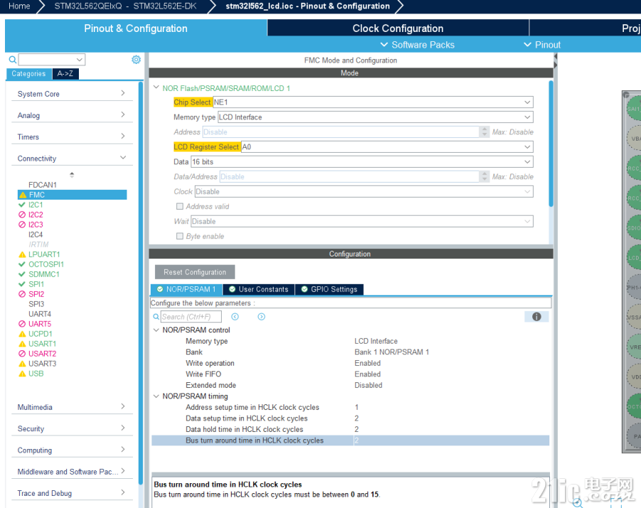
下面接着设置FMC接口参数,参考bsp库的代码例子。

然后就是LCD接口的电源控制GPIO,复位引脚GPIO,背光控制GPIO设置。

设置之后就是生成代码工程了。

下面接着就是编写lcd屏的驱动代码了。首先就是LCD的初始化代码,这里参考BSP的驱动初始化。
读写LCD屏寄存器代码如下:
#define LCD_REGISTER_ADDR               FMC_BANK1_1
#define LCD_DATA_ADDR                   (FMC_BANK1_1 | 0x00000002UL)

/**
  * [@brief](home.php?mod=space&uid=247401)  Reset ST7789H2 and activate backlight.
  * @retval None.
  */
void ST7789H2_PowerUp(void)
{
    /* Power on the ST7789H2 */
    HAL_GPIO_WritePin(LCD_POWER_GPIO_PORT, LCD_POWER_GPIO_PIN, GPIO_PIN_RESET);

    /* Reset the ST7789H2 */
    HAL_GPIO_WritePin(LCD_RESET_GPIO_PORT, LCD_RESET_GPIO_PIN, GPIO_PIN_RESET);
    HAL_Delay(1); /* wait at least 10us according ST7789H2 datasheet */
    HAL_GPIO_WritePin(LCD_RESET_GPIO_PORT, LCD_RESET_GPIO_PIN, GPIO_PIN_SET);
    HAL_Delay(120); /* wait maximum 120ms according ST7789H2 datasheet */

    /* Enable backlight */
    HAL_GPIO_WritePin(LCD_BACKLIGHT_GPIO_PORT, LCD_BACKLIGHT_GPIO_PIN, GPIO_PIN_SET);

}
/**
  * [@brief](home.php?mod=space&uid=247401)  Reset ST7789H2 and deactivate backlight.
  * @retval BSP status.
  */
void ST7789H2_PowerDown(void)
{
    /* Deactivate backlight */
    HAL_GPIO_WritePin(LCD_BACKLIGHT_GPIO_PORT, LCD_BACKLIGHT_GPIO_PIN, GPIO_PIN_RESET);

    /* Reset the ST7789H2 */
    HAL_GPIO_WritePin(LCD_RESET_GPIO_PORT, LCD_RESET_GPIO_PIN, GPIO_PIN_RESET);

    /* Power down the ST7789H2 */
    HAL_GPIO_WritePin(LCD_POWER_GPIO_PORT, LCD_POWER_GPIO_PIN, GPIO_PIN_SET);
}

/**
  * @brief  Write 16bit values in registers of the device through BUS.
  * @param  DevAddr Device address on Bus.
  * @param  Reg     The target register start address to write.
  * @param  pData   Pointer to data buffer.
  * @param  Length  Number of data.
  * @retval BSP status.
  */
int32_t LCD_FMC_WriteReg16(uint16_t Reg, uint16_t *pData, uint16_t Length)
{
  int32_t  ret = 0;
  uint32_t i = 0;

  if ((pData == NULL) && (Length))
  {
    ret = 1;
  }
  else
  {
    /* Write register address */
    *(__IO uint16_t *)LCD_REGISTER_ADDR = Reg;
    while (i < Length)
    {
      /* Write register value */
      *(__IO uint16_t *)LCD_DATA_ADDR = pData[i++];
    }
  }

  return ret;
}

/**
  * @brief  Read 16bit values in registers of the device through BUS.
  * @param  DevAddr Device address on Bus.
  * @param  Reg     The target register start address to read.
  * @param  pData   Pointer to data buffer.
  * @param  Length  Number of data.
  * @retval BSP status.
  */
int32_t LCD_FMC_ReadReg16(uint16_t Reg, uint16_t *pData, uint16_t Length)
{
  int32_t  ret = 0;
  uint32_t i = 0;

  if ((pData == NULL) && (Length))
  {
    ret = 1;
  }
  else
  {
    /* Write register address */
    *(__IO uint16_t *)LCD_REGISTER_ADDR = Reg;
    while (i < Length)
    {
      pData[i++] = *(__IO uint16_t *)LCD_DATA_ADDR;
    }
  }

  return ret;
}

/**
  * @brief  Send 16bit values to device through BUS.
  * @param  pData   Pointer to data buffer.
  * @param  Length  Number of data.
  * @retval BSP status.
  */
int32_t LCD_FMC_SendData(uint16_t *pData, uint32_t Length)
{
  int32_t  ret = 0;
  uint32_t i = 0;

  if ((pData == NULL) && (Length))
  {
    ret = 1;
  }
  else
  {
    while (i < Length)
    {
      /* Send value */
      *(__IO uint16_t *)LCD_DATA_ADDR = pData[i ++];
    }
  }

  return ret;
}
LCD初始化配置代码如下:
const uint16_t    lcd_st7789h2_init_tbl[] =
{
    ST7789H2_SLEEP_IN,      (10<<8) +0,      /* Sleep In Command */
    ST7789H2_SW_RESET,      (100<<8)+0,      /* SW Reset Command */
    ST7789H2_SLEEP_OUT,     (100<<8)+0,      /* Sleep Out Command */
    ST7789H2_MADCTL,        1,      0x00, /* MY = 0, MX = 0, MV = 0 */
                                    //0xA0; /* MY = 1, MX = 0, MV = 1 */
                                    //0xC0; /* MY = 1, MX = 1, MV = 0 */
                                    //0x60; /* MY = 0, MX = 1, MV = 1 */
    ST7789H2_COLOR_MODE,    1,      0x05,   //rgb565
    ST7789H2_DISPLAY_INV_ON,0,              /* Display inversion On */
    ST7789H2_CASET,         4,      0x00,0x00,0x00,0xef,  //0x00,0x50,0x01,0x3f,    //      /* Set Column address CASET */
    ST7789H2_RASET,         4,      0x00,0x00,0x00,0xef,  //0x00,0x50,0x01,0x3f,    //      /* Set Row address RASET */
    ST7789H2_PORCH_CTRL,    5,      0x0c,0x0c,0x00,0x33,0x33,       /* PORCH control setting */
    ST7789H2_GATE_CTRL,     1,      0x35,
    ST7789H2_VCOM_SET,      1,      0x1f,       /* VCOM setting */
    ST7789H2_LCM_CTRL,      1,      0x2c,       /* LCM Control setting */
    ST7789H2_VDV_VRH_EN,    2,      0x01,0xc3,  /* VDV and VRH Command Enable */
    ST7789H2_VDV_SET,       1,      0x20,       /* VDV Set */
    ST7789H2_FR_CTRL,       1,      0x0f,       /* Frame Rate Control in normal mode */
    ST7789H2_POWER_CTRL,    2,      0xa4,0xa1,  /* Power Control */
    ST7789H2_PV_GAMMA_CTRL, 14,     0xd0,0x08,0x11,0x08,0x0c,0x15,0x39,0x33,0x50,0x36,0x13,0x14,0x29,0x2d,  /* Positive Voltage Gamma Control */
    ST7789H2_NV_GAMMA_CTRL, 14,     0xd0,0x08,0x10,0x08,0x06,0x06,0x39,0x44,0x51,0x0b,0x16,0x14,0x2f,0x31,  /* Negative Voltage Gamma Control */
    ST7789H2_TE_LINE_ON,    1,      0x01,   /* Tearing Effect Line On: Option (00h:VSYNC Interface OFF, 01h:VSYNC Interface ON) */
    ST7789H2_DISPLAY_ON,    0,
    0,
};

/**
  * @brief  Initialize the st7789h2 LCD component.
  * @retval Component status.
  */
uint32_t ST7789H2_Init(void *args)
{
    uint16_t * ptr;
    uint16_t   cmd_reg,data_len,t;

    ST7789H2_PowerUp();
    ptr = (uint16_t *)lcd_st7789h2_init_tbl;
    cmd_reg = *ptr++;
    while(cmd_reg)
    {
        data_len = *ptr++;
        t = data_len >> 8;
        data_len &= 0xff;
        LCD_FMC_WriteReg16(cmd_reg,ptr,data_len);
        if(t)   HAL_Delay(t);
        ptr += data_len;
        cmd_reg = *ptr++;
    }

    return 0;
}
初始化需要注意:
要打开LCD电源GPIO控制,复位一下LCD引脚,接着打开背光GPIO。
再就是配置LCD寄存器时ST7789H2_SLEEP_IN,ST7789H2_SW_RESET,ST7789H2_SLEEP_OUT命令后要延时一下。
下面就是绘图,画点,填充函数:
int32_t ST7789H2_SetCursor(uint16_t Xs, uint16_t Ys, uint16_t Xe, uint16_t Ye)
{
    uint16_t parameter[8];

    parameter[0] = (Xs >> 8);
    parameter[1] = (Xs & 0xff);
    parameter[2] = (Xe >> 8);
    parameter[3] = (Xe & 0xff);
    LCD_FMC_WriteReg16(ST7789H2_CASET,parameter,4);

    parameter[0] = (Ys >> 8);
    parameter[1] = (Ys & 0xff);
    parameter[2] = (Ye >> 8);
    parameter[3] = (Ye & 0xff);
    LCD_FMC_WriteReg16(ST7789H2_RASET,parameter,4);

    LCD_FMC_WriteReg16(ST7789H2_WRITE_RAM,parameter,0);
    return 0;
}

uint32_t ST7789H2_DrawBitmap (uint8_t mode, int16_t x,  int16_t y,  uint16_t w, uint16_t h, const uint8_t *bmp)
{
    ST7789H2_SetCursor(x,y,x+w-1,y+h-1);
    /* Write GRAM */
    LCD_FMC_SendData((uint16_t *)bmp, w*h);

    return 0;
}

uint32_t ST7789H2_DrawPixel (int16_t x,  int16_t y,  lcd_color_t color)
{
    ST7789H2_SetCursor(x,y,x,y);
    LCD_FMC_SendData((uint16_t *)&color, 1);
    return 0;
}

uint32_t ST7789H2_Fill (int16_t x,  int16_t y,  uint16_t w, uint16_t h, lcd_color_t color)
{
    volatile uint32_t i;
    ST7789H2_SetCursor(x,y,x+w-1,y+h-1);
    for(i=0;i<w*h;i++)
    {
        LCD_FMC_SendData((uint16_t *)&color, 1);
    }
    return 0;
}
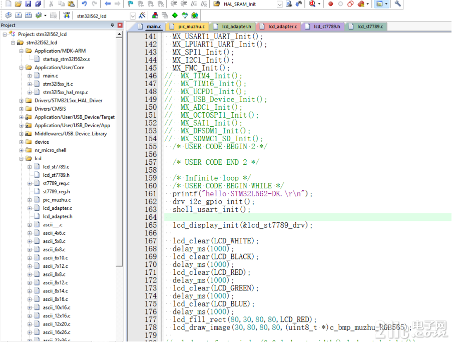
之后就可以在LCD上绘图了。

实际下载效果如下:

 附件:stm32l562_lcd.zip