- void wk_usart4_init(void)
- {
- /* add user code begin usart4_init 0 */
- /* enable usart4 periph clock */
- crm_periph_clock_enable(CRM_USART4_PERIPH_CLOCK, TRUE);
- crm_periph_clock_enable(CRM_GPIOA_PERIPH_CLOCK, TRUE);
- /* add user code end usart4_init 0 */
- gpio_init_type gpio_init_struct;
- gpio_default_para_init(&gpio_init_struct);
- /* add user code begin usart4_init 1 */
- /* add user code end usart4_init 1 */
- /* configure the TX pin */
- gpio_pin_mux_config(GPIOA, GPIO_PINS_SOURCE0, GPIO_MUX_4);
- gpio_init_struct.gpio_drive_strength = GPIO_DRIVE_STRENGTH_MODERATE;
- gpio_init_struct.gpio_out_type = GPIO_OUTPUT_PUSH_PULL;
- gpio_init_struct.gpio_mode = GPIO_MODE_MUX;
- gpio_init_struct.gpio_pins = GPIO_PINS_0;
- gpio_init_struct.gpio_pull = GPIO_PULL_NONE;
- gpio_init(GPIOA, &gpio_init_struct);
- /* configure the RX pin */
- gpio_pin_mux_config(GPIOA, GPIO_PINS_SOURCE1, GPIO_MUX_4);
- gpio_init_struct.gpio_drive_strength = GPIO_DRIVE_STRENGTH_MODERATE;
- gpio_init_struct.gpio_out_type = GPIO_OUTPUT_PUSH_PULL;
- gpio_init_struct.gpio_mode = GPIO_MODE_MUX;
- gpio_init_struct.gpio_pins = GPIO_PINS_1;
- gpio_init_struct.gpio_pull = GPIO_PULL_NONE;
- gpio_init(GPIOA, &gpio_init_struct);
- nvic_irq_enable(USART4_3_IRQn, 0, 0);
- /* configure param */
- usart_init(USART4, 115200, USART_DATA_8BITS, USART_STOP_1_BIT);
- usart_transmitter_enable(USART4, TRUE);
- usart_receiver_enable(USART4, TRUE);
- usart_parity_selection_config(USART4, USART_PARITY_NONE);
- usart_hardware_flow_control_set(USART4, USART_HARDWARE_FLOW_NONE);
- /**
- * Users need to configure USART4 interrupt functions according to the actual application.
- * 1. Call the below function to enable the corresponding USART4 interrupt.
- * --usart_interrupt_enable(...)
- * 2. Add the user's interrupt handler code into the below function in the at32l021_int.c file.
- * --void USART4_3_IRQHandler(void)
- */
- /* add user code begin usart4_init 2 */
- usart_interrupt_enable(USART4, USART_RDBF_INT, TRUE);
- /* add user code end usart4_init 2 */
-
- usart_enable(USART4, TRUE);
-
- /* add user code begin usart4_init 3 */
-
- /* add user code end usart4_init 3 */
- }
- void USART4_3_IRQHandler(void)
- {
- char c;
- if(usart_flag_get(USART4, USART_RDBF_FLAG) != RESET)
- {
- /* read one byte from the receive data register */
- c=usart_data_receive(USART4);
- usart4_rx_buffer[usart4_rx_counter++] = c;
- printf("%c",c);
-
- if(strstr((char*)usart4_rx_buffer,"S1")){
- at32_led_toggle(LED2);
- Clear_Buff();
- show_digit();
- };
- }
- }
还可以实现AT-START-L021对蓝牙模块的控制
3.通过USART4向蓝牙模块发送指令函数
- void PB03_AT_Send(const char *cmd )
- {
- if (cmd == NULL) {
- // 处理错误或返回
- return;
- }
- Clear_Buff();
- uart4_receive_complete_flag = FALSE; // 根据需要设置标志
- while (*cmd) {
- while(usart_flag_get(USART4, USART_TDBE_FLAG) == RESET);
- usart_data_transmit(USART4, (uint8_t)*cmd++);
- while(usart_flag_get(USART4, USART_TDC_FLAG) == RESET);
- }
- }
AT+LEDTEST=1
板载的5个LED循环点亮,可以用于测试
- void PB03_LEDTEST( uint8_t timeout )
- {
- PB03_AT_Send ( "AT+LEDTEST=1\r\n" );
- PB03_wait_complete(timeout,(char*)__func__);
- }
-
- void PB03_wait_complete(uint8_t timeout,char* fun)
- {
- uint8_t i;
-
- for(i = 0; i <= timeout; i++)
- {
- //printf("%d,%s\r\n",i,usart4_rx_buffer);
- if (strstr( usart4_rx_buffer , "OK" ))
- {
- //printf("\r\n %s success\r\n",fun);
- Clear_Buff(); //
- return;
- }
- delay_ms(10);
- }
- //printf("%s timeout\r\n",fun);
- }
- void PB03_LED_CONTRL(PNTypeDef pinnum,uint8_t on,uint8_t timeout)
- {
- char cmd[22];
- sprintf(cmd,"AT+SYSIOMAP=1,%d\r\n",LED_PINS[pinnum]);
-
- PB03_AT_Send(cmd);
- PB03_wait_complete(timeout,(char*)cmd);
-
- if(on==1||on==0){
- sprintf(cmd,"AT+SYSGPIOWRITE=0,%d\r\n",on);
- PB03_AT_Send(cmd);
- PB03_wait_complete(timeout,(char*)cmd);
- }else return;
- }
- void PBC03_PWM_CONTRL(uint8_t timeout)
- {
- char cmd[30];
- sprintf(cmd,"AT+PWMCFG=0,100000,50000\r\n");
-
- PB03_AT_Send(cmd);
- PB03_wait_complete(timeout,(char*)__func__);
- }
- void show_digit(void)
- {
- static uint8_t i;
- char buff[3];
- sprintf(buff,"%d",i++);
- GUI_WriteASCII_BIG(98,60,(unsigned char*)buff,VGA_RED,VGA_BLACK);
- }
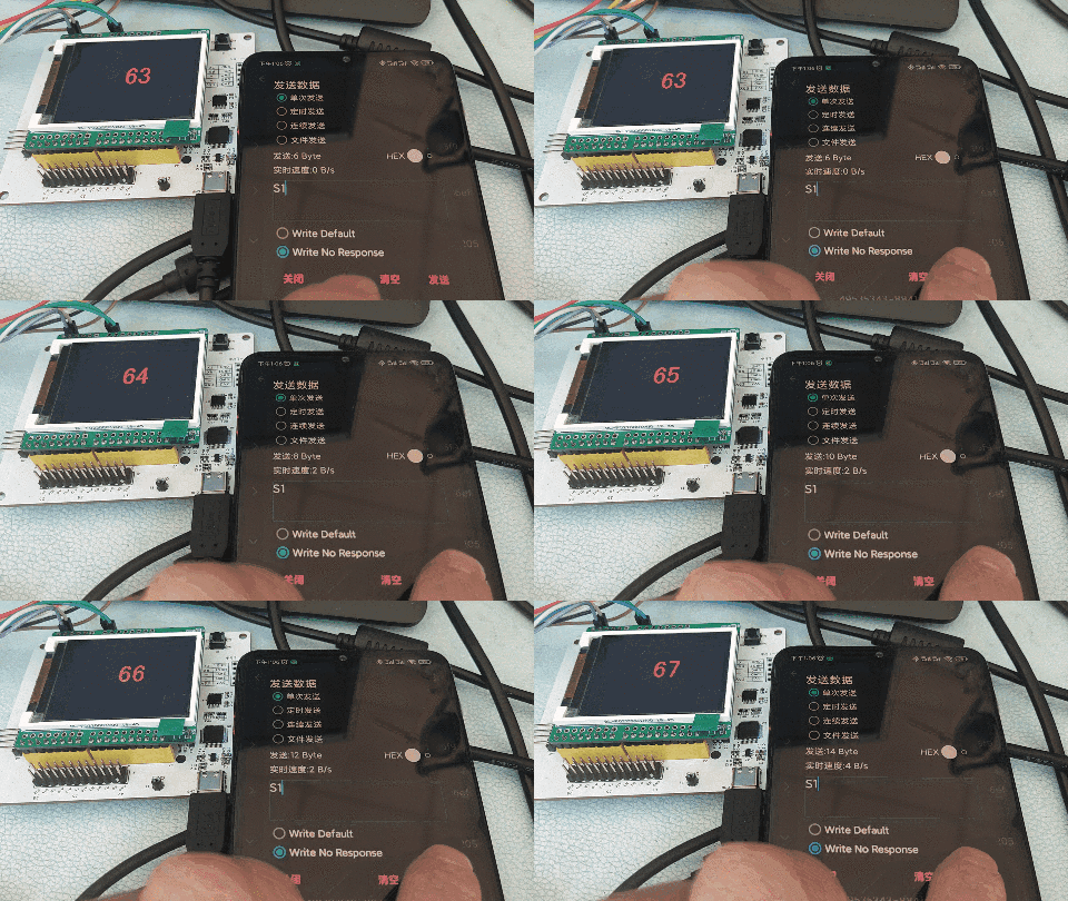
1.手机连接蓝牙模块,向蓝牙写入S1;
2.蓝牙通过串口将S1转发给AT-START-L021;
3.AT-START-L021判断收到S1,改变LCD显示:
