[DemoCode下载] GP2Y1010AU0F

[复制链接]
 楼主| a_ziliu 发表于 2017-4-5 11:17 | 显示全部楼层 |阅读模式
gp, AC, AD, dc, IO
gp2y1010au_appl_e.pdf (320.78 KB, 下载次数: 6)
NUC230_240 GP2Y1010AU0F.zip (420.38 KB, 下载次数: 9)
使用ADC及GPIO控制GP2Y1010AU0F
公式及原理參考
http://www.howmuchsnow.com/arduino/airquality/
測試得到的資料和空氣品質對照:

3000 + = 很差

1050-3000 = 差

300-1050 = 一般

150-300 = 好

75-150 = 很好

0-75 = 非常好
天灵灵地灵灵 发表于 2017-4-6 13:45 | 显示全部楼层
空气质量检测的方案?
huangcunxiake 发表于 2017-4-6 19:50 | 显示全部楼层
下载学习学习。
huangcunxiake 发表于 2017-4-6 19:50 | 显示全部楼层
  1. #include <stdio.h>
  2. #include "NUC230_240.h"
  3. /*
  4. PIN DEFINE
  5. Sharp pin 1 (V-LED)   => 5V (connected to 150ohm resister)
  6. Sharp pin 2 (LED-GND) => GND pin
  7. Sharp pin 3 (LED)     => PA1 pin
  8. Sharp pin 4 (S-GND)   => GND pin
  9. Sharp pin 5 (Vo)      => PA0 pin
  10. Sharp pin 6 (Vcc)     => 5V
  11. */

  12. /*---------------------------------------------------------------------------------------------------------*/
  13. /* Define global variables and constants                                                                   */
  14. /*---------------------------------------------------------------------------------------------------------*/
  15. volatile uint32_t g_u32AdcIntFlag;


  16. void ADC_IRQHandler(void)
  17. {
  18.           PA2=PA2^1;
  19.     g_u32AdcIntFlag = 1;
  20.     ADC_CLR_INT_FLAG(ADC, ADC_ADF_INT); /* clear the A/D conversion flag */
  21. }

  22. /*---------------------------------------------------------------------------------------------------------*/
  23. /* MAIN function                                                                                           */
  24. /*---------------------------------------------------------------------------------------------------------*/
  25. int main(void)
  26. {
  27.    int32_t  i32ConversionData;
  28.        
  29. float calcVoltage,dustDensity;
  30.     /* Unlock protected registers */
  31.     SYS_UnlockReg();   
  32.             /* Enable ADC module clock */
  33.     CLK_EnableModuleClock(ADC_MODULE);
  34.     SystemCoreClockUpdate();  

  35.         /* ADC clock source is 22.1184MHz, set divider to 7, ADC clock is 22.1184/7 MHz */
  36.     CLK_SetModuleClock(ADC_MODULE, CLK_CLKSEL1_ADC_S_HIRC, CLK_CLKDIV_ADC(11));

  37.         /* Disable the GPA0 - GPA3 digital input path to avoid the leakage current. */
  38.     GPIO_DISABLE_DIGITAL_PATH(PA, 0x1);
  39.   
  40.         /* Configure the GPA0 ADC analog input pins */
  41.     SYS->GPA_MFP &= ~(SYS_GPA_MFP_PA0_Msk ) ;
  42.     SYS->GPA_MFP |= SYS_GPA_MFP_PA0_ADC0  ;
  43.     SYS->ALT_MFP1 = 0;
  44.        
  45.         /* Set the ADC operation mode as single, input mode as single-end and enable the analog input channel 2 */
  46.             ADC_Open(ADC, ADC_ADCR_DIFFEN_SINGLE_END, ADC_ADCR_ADMD_SINGLE, 0x1 << 0);

  47.             /* Power on ADC module */
  48.             ADC_POWER_ON(ADC);

  49.             /* Clear the A/D interrupt flag for safe */
  50.             ADC_CLR_INT_FLAG(ADC, ADC_ADF_INT);

  51.             /* Enable the ADC interrupt */
  52.             ADC_EnableInt(ADC, ADC_ADF_INT);
  53.             NVIC_EnableIRQ(ADC_IRQn);

  54.        
  55.        
  56.     /* Configure PA.1 as Output mode*/
  57.     GPIO_SetMode(PA, BIT1, GPIO_PMD_OUTPUT);
  58.     PA1=1;
  59.                 while(1)
  60.                 {
  61.                                    
  62.             
  63.                         PA1=0; // power on the LED       
  64.       g_u32AdcIntFlag = 0;
  65.                         CLK_SysTickDelay(250); /* Reset the ADC interrupt indicator and Start A/D conversion */
  66.       ADC_START_CONV(ADC);                       
  67.                   CLK_SysTickDelay(3200);
  68.       /* Wait ADC interrupt (g_u32AdcIntFlag will be set at IRQ_Handler function)*/
  69.       while(g_u32AdcIntFlag == 0);
  70.                                /* Get the conversion result of the ADC channel 0 */
  71.                         i32ConversionData = ADC_GET_CONVERSION_DATA(ADC, 0);
  72.                         PA1=1;
  73.                          // 0 - 5V mapped to 0 - 1023 integer values
  74. // recover voltage
  75. calcVoltage = (float)i32ConversionData * (5.0 / 1024.0);
  76. // linear eqaution taken from http://www.howmuchsnow.com/arduino/airquality/
  77.                         dustDensity = 0.17 * calcVoltage - 0.1;
  78.                         printf("Dust Density: ");
  79.       printf("%.2f",dustDensity * 1000); // ???????????????( ug/m3 )
  80.       printf(" ug/m3 \n\r");
  81.                         CLK_SysTickDelay(100000);
  82.                 }
  83.                
  84. }

  85. /*** (C) COPYRIGHT 2014 Nuvoton Technology Corp. ***/
huangcunxiake 发表于 2017-4-6 19:52 | 显示全部楼层
The unit is amazingly sensitive. It easily sees the dust kicked up from walking on a rug or the vapors from cooking. Looking at the graphs below you can see some interesting things. First you can see that things settle down at night when people are not walking around. You can see around noon that my daughter cooked lunch. It's surprising how long it takes for the fine particles to settle down.
airquality1.jpg
airquality2.jpg


ApproachSet UpAn Arduino Ethernet is connected to the Sharp sensor following the schematic in the Sharp GP2Y1010AU0F Spec sheet. The LED connected to pin 2 is turned on, after 0.28ms the analog pin A0 connected to Vo is sampled. 0.04ms later, the LED is turned off and 9.680ms is waited before the 10ms sequence is repeated (Arduino Source Code).Sharp pin 1 (V-LED)   => 5V (connected to 150ohm resister)Sharp pin 2 (LED-GND) => Arduino GND pinSharp pin 3 (LED)     => Arduino pin 2Sharp pin 4 (S-GND)   => Arduino GND pinSharp pin 5 (Vo)      => Arduino A0 pinSharp pin 6 (Vcc)     => 5V connector.jpg fan.jpg
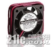
I used a small 40mm fan to help make sure air was circulated thru the Sharp sensor. This probably is not required, but since I am mounting one of the sensors outside in a radiation shield, I wanted to make sure I saw any pollen floating by.
Testing and Calibration 100_1396a.jpg The Pancake test :-)
When you read the Sharp GP2Y1010AU0F Spec sheet Fig. 3 shows a Dust density (mg/m^3) versus voltage graph. But the graph starts at over 0.5 VDC. Unfortunately for most of my tests, the voltage was much lower. I entered the values off the graph and calculated a linear equation to approximate the mg/m^3 values.
dustvoltage.jpg
With the inexpensive Sharp sensor, I wanted to see how sensitive it was and I wanted to try to correlate the voltage to some meaningful metric. I tried a quick match test (blew out a match and let the smoke go over the sensor). The smoke quickly saturated the sensor. I wanted a longer term test. After seeing that the dylos sensor could see my daughter cooking lunch, I decided to do a "pan cake" test. Did you ever notice that after making pancakes in an old cast iron fry pan with butter, that the kitchen hazes up. I set up both the Dylos and Sharp sensors to capture the data to Pachube. This allowed me to compare/calibrate the sensors.
sharp1.gif dylos.gif
The two graphs are amazingly similar. Applying a simple offset and multiplication factor allowed the data to be overlaid.
(V-0.0356)*120000
The interesting thing is that Dylos has a chart to rate your air relative to other residential environments. The pancake test exceed these by 50X. So there is some question of how sensitive the Sharp unit is at very low particle counts.
Air Quality Chart - Small Count Reading (0.5 micron)+3000 +     = VERY POOR1050-3000  = POOR300-1050   = FAIR150-300    = GOOD75-150     = VERY GOOD0-75       = EXCELLENT

玛尼玛尼哄 发表于 2017-4-6 21:18 | 显示全部楼层
这个设备是测PM2.5的?
稳稳の幸福 发表于 2017-4-9 16:45 | 显示全部楼层
可以直接定义个曲线,用颜色变化表示污染程度。
您需要登录后才可以回帖 登录 | 注册

本版积分规则

100

主题

310

帖子

6

粉丝
快速回复 在线客服 返回列表 返回顶部