- void LED_Initialize(GPIO_Module* GPIOx, uint16_t pin)
- {
- GPIO_InitType GPIO_InitStructure;
- if(GPIOx == GPIOA)
- {
- RCC_AHB_Peripheral_Clock_Enable(RCC_AHB_PERIPH_GPIOA);
- }
- else if(GPIOx == GPIOB)
- {
- RCC_AHB_Peripheral_Clock_Enable(RCC_AHB_PERIPH_GPIOB);
- }
- else if(GPIOx == GPIOC)
- {
- RCC_AHB_Peripheral_Clock_Enable(RCC_AHB_PERIPH_GPIOC);
- }
- else
- {
- RCC_AHB_Peripheral_Clock_Enable(RCC_AHB_PERIPH_GPIOD);
- }
-
- if(pin < GPIO_PIN_ALL)
- {
- GPIO_Structure_Initialize(&GPIO_InitStructure);
- GPIO_InitStructure.Pin = pin;
- GPIO_InitStructure.GPIO_Mode = GPIO_MODE_OUT_PP;
- GPIO_InitStructure.GPIO_Current = GPIO_DS_4MA;
- GPIO_Peripheral_Initialize(GPIOx, &GPIO_InitStructure);
- }
- }
- void LED_Toggle(GPIO_Module* GPIOx, uint16_t pin)
- {
- GPIO_Pin_Toggle(GPIOx, pin);;
- }
- {
- GPIO_Pins_Set(GPIOx, pin);
- }
- void LED_Off(GPIO_Module* GPIOx,uint16_t pin)
- {
- GPIO_Pins_Reset(GPIOx, pin);
- }
- // mian test
- int main(void)
- {
- LED_Initialize(LED1_GPIO_PORT, LED1_GPIO_PIN | LED2_GPIO_PIN | LED3_GPIO_PIN);
- LED_Off(LED1_GPIO_PORT, LED1_GPIO_PIN | LED2_GPIO_PIN | LED3_GPIO_PIN);
- while(1)
- {
- LED_Toggle(LED1_GPIO_PORT, LED1_GPIO_PIN);
- LED_Toggle(LED2_GPIO_PORT, LED2_GPIO_PIN);
- LED_Toggle(LED3_GPIO_PORT, LED3_GPIO_PIN);
- SysTick_Delay_Ms(1000);
- }
- }
- void Key_Input_Initialize(GPIO_Module* GPIOx, uint16_t pin)
- {
- GPIO_InitType GPIO_InitStructure;
- if(GPIOx == GPIOA)
- {
- RCC_AHB_Peripheral_Clock_Enable(RCC_AHB_PERIPH_GPIOA);
- }
- else if(GPIOx == GPIOB)
- {
- RCC_AHB_Peripheral_Clock_Enable(RCC_AHB_PERIPH_GPIOB);
- }
- else if(GPIOx == GPIOC)
- {
- RCC_AHB_Peripheral_Clock_Enable(RCC_AHB_PERIPH_GPIOC);
- }
- else
- {
- RCC_AHB_Peripheral_Clock_Enable(RCC_AHB_PERIPH_GPIOD);
- }
-
- if(pin < GPIO_PIN_ALL)
- {
- GPIO_Structure_Initialize(&GPIO_InitStructure);
- GPIO_InitStructure.Pin = pin;
- GPIO_InitStructure.GPIO_Mode = GPIO_MODE_INPUT;
- GPIO_InitStructure.GPIO_Pull = GPIO_PULL_UP;
- /* Initialize GPIO */
- GPIO_Peripheral_Initialize(GPIOx, &GPIO_InitStructure);
- }
- }
- void Key_Input_Initialize(GPIO_Module* GPIOx, uint16_t pin)
- {
- /* Define a structure of type GPIO_InitType */
- GPIO_InitType GPIO_InitStructure;
-
- /* Enable KEY related GPIO peripheral clock */
- if(GPIOx == GPIOA)
- {
- RCC_AHB_Peripheral_Clock_Enable(RCC_AHB_PERIPH_GPIOA);
- }
- else if(GPIOx == GPIOB)
- {
- RCC_AHB_Peripheral_Clock_Enable(RCC_AHB_PERIPH_GPIOB);
- }
- else if(GPIOx == GPIOC)
- {
- RCC_AHB_Peripheral_Clock_Enable(RCC_AHB_PERIPH_GPIOC);
- }
- else
- {
- RCC_AHB_Peripheral_Clock_Enable(RCC_AHB_PERIPH_GPIOD);
- }
-
- if(pin < GPIO_PIN_ALL)
- {
- GPIO_Structure_Initialize(&GPIO_InitStructure);
- GPIO_InitStructure.Pin = pin;
- GPIO_InitStructure.GPIO_Mode = GPIO_MODE_INPUT;
- GPIO_InitStructure.GPIO_Pull = GPIO_PULL_UP;
- GPIO_Peripheral_Initialize(GPIOx, &GPIO_InitStructure);
- }
- }
- // main test
- int main(void)
- {
- LED_Initialize(LED1_GPIO_PORT, LED1_GPIO_PIN | LED2_GPIO_PIN);
- Key_Input_Initialize(KEY3_PORT, KEY3_PIN);
- while(1)
- {
- if(GPIO_Input_Pin_Data_Get(KEY3_PORT, KEY3_PIN) == PIN_RESET)
- {
- LED_On(LED1_GPIO_PORT, LED1_GPIO_PIN);
- LED_Off(LED2_GPIO_PORT, LED2_GPIO_PIN);
- LED_Off(LED3_GPIO_PORT, LED3_GPIO_PIN);
- }
- }
- uint32_t BSTIMClockFrequency = 0;
- void GPIO_Config(void)
- {
- GPIO_InitType GPIO_InitStructure;
- GPIO_Structure_Initialize(&GPIO_InitStructure);
- GPIO_InitStructure.Pin = GPIO_PIN_6;
- GPIO_InitStructure.GPIO_Mode = GPIO_MODE_OUT_PP;
- GPIO_InitStructure.GPIO_Slew_Rate = GPIO_SLEW_RATE_FAST;
- GPIO_Peripheral_Initialize(GPIOB, &GPIO_InitStructure);
- }
- int main(void)
- {
- GPIO_Config();
- BSTIMClockFrequency = Common_BSTIM_RCC_Initialize(TIM6, RCC_HCLK_DIV4);
- Common_TIM_NVIC_Initialize(TIM6_IRQn, ENABLE);
- Common_TIM_Base_Initialize(TIM6, 65535, 0);
- TIM_Base_Reload_Mode_Set(TIM6, TIM_PSC_RELOAD_MODE_IMMEDIATE);
- TIM_Interrupt_Enable(TIM6, TIM_INT_UPDATE);
- TIM_On(TIM6);
- }
- void TIM6_IRQHandler(void)
- {
- if (TIM_Interrupt_Status_Get(TIM6, TIM_INT_UPDATE) != RESET)
- {
- TIM_Interrupt_Status_Clear(TIM6, TIM_INT_UPDATE);
- GPIO_Pin_Toggle(GPIOB, GPIO_PIN_6);
- }
- }
- void GPIO_Configuration(void)
- {
- GPIO_InitType GPIO_InitStructure;
- GPIO_Structure_Initialize(&GPIO_InitStructure);
- GPIO_InitStructure.Pin = USARTx_TxPin;
- GPIO_InitStructure.GPIO_Mode = GPIO_MODE_AF_PP;
- GPIO_InitStructure.GPIO_Alternate = USARTx_Tx_GPIO_AF;
- GPIO_Peripheral_Initialize(USARTx_GPIO, &GPIO_InitStructure);
- GPIO_InitStructure.Pin = USARTx_RxPin;
- GPIO_InitStructure.GPIO_Alternate = USARTx_Rx_GPIO_AF;
- GPIO_Peripheral_Initialize(USARTx_GPIO, &GPIO_InitStructure);
- }
- void RCC_Configuration(void)
- {
- GPIO_AHBClkCmd(USARTx_GPIO_CLK);
- USART_APBxClkCmd(USARTx_CLK);
- }
- void UART_Configuration(void)
- {
- USART_InitType USART_InitStructure;
- USART_InitStructure.BaudRate = 115200;
- USART_InitStructure.WordLength = USART_WL_8B;
- USART_InitStructure.StopBits = USART_STPB_1;
- USART_InitStructure.Parity = USART_PE_NO;
- USART_InitStructure.HardwareFlowControl = USART_HFCTRL_NONE;
- USART_InitStructure.Mode = USART_MODE_RX | USART_MODE_TX;
- /* Configure USARTx */
- USART_Initializes(USARTx, &USART_InitStructure);
- /* Enable the USARTx */
- USART_Enable(USARTx);
- }
- int main(void)
- {
- RCC_ClocksType RCC_ClocksStatus;
- RCC_Configuration();
- GPIO_Configuration();
- UART_Configuration(void);
- RCC_Clocks_Frequencies_Value_Get(&RCC_ClocksStatus);
- printf("\n\rUSART Printf Example: retarget the C library printf function to the USART\n\r");
- while (1)
- {
- }
- }
- int fputc(int ch, FILE* f)
- {
- USART_Data_Send(USARTx, (uint8_t)ch);
- while (USART_Flag_Status_Get(USARTx, USART_FLAG_TXDE) == RESET);
- return (ch);
- }
- #ifdef USE_FULL_ASSERT
- void assert_failed(const uint8_t* expr, const uint8_t* file, uint32_t line)
- {
- /* User can add his own implementation to report the file name and line number,
- ex: printf("Wrong parameters value: file %s on line %d\r\n", file, line) */
- /* Infinite loop */
- while (1)
- {
- }
- }
- #endif
- void CAN_CONFIG(void)
- {
- RCC_APB1_Peripheral_Clock_Enable(RCC_APB1_PERIPH_CAN);
- CAN_NVIC_Configuration();
- CAN_GPIO_Configuration();
-
- CAN_Reset(CAN);
- CAN_Structure_Initializes(&CAN_InitStructure);
- CAN_InitStructure.TTCM = DISABLE;
- CAN_InitStructure.ABOM = DISABLE;
- CAN_InitStructure.AWKUM = DISABLE;
- CAN_InitStructure.NART = DISABLE;
- CAN_InitStructure.RFLM = DISABLE;
- CAN_InitStructure.TXFP = ENABLE;
- CAN_InitStructure.OperatingMode = CAN_LOOPBACK_MODE;
- CAN_InitStructure.RSJW = CAN_RSJW_1TQ;
- CAN_InitStructure.TBS1 = CAN_TBS1_8TQ;
- CAN_InitStructure.TBS2 = CAN_TBS2_7TQ;
- CAN_InitStructure.BaudRatePrescaler = 4;
- CAN_Initializes(CAN, &CAN_InitStructure);
- CAN_FilterInitStructure.Filter_Num = 0;
- CAN_FilterInitStructure.Filter_Mode = CAN_FILTER_IDLISTMODE;
- CAN_FilterInitStructure.Filter_Scale = CAN_FILTER_32BITSCALE;
- CAN_FilterInitStructure.Filter_HighId = 0x8000;
- CAN_FilterInitStructure.Filter_LowId = 0x0000;
- CAN_FilterInitStructure.FilterMask_HighId = 0x4000;
- CAN_FilterInitStructure.FilterMask_LowId = 0x0000;
- CAN_FilterInitStructure.Filter_FIFOAssignment = CAN_FIFO0;
- CAN_FilterInitStructure.Filter_Act = ENABLE;
- CAN_Filter_Initializes(&CAN_FilterInitStructure);
- CAN_Config_Interrupt_Enable(CAN, CAN_INT_FMP0);
- }
- void CAN_NVIC_Configuration(void)
- {
- NVIC_InitType NVIC_InitStructure;
- NVIC_Initializes(&NVIC_InitStructure);
- NVIC_InitStructure.NVIC_IRQChannel = CAN_RX0_IRQn;
- NVIC_InitStructure.NVIC_IRQChannelPreemptionPriority = 0x0;
- NVIC_InitStructure.NVIC_IRQChannelSubPriority = 0x1;
- NVIC_InitStructure.NVIC_IRQChannelCmd = ENABLE;
- NVIC_Initializes(&NVIC_InitStructure);
- }
- void CAN_GPIO_Configuration(void)
- {
- GPIO_InitType GPIO_InitStructure;
- GPIO_Structure_Initialize(&GPIO_InitStructure);
-
- RCC_AHB_Peripheral_Clock_Enable(RCC_AHB_PERIPH_GPIOB);
- RCC_APB2_Peripheral_Clock_Enable(RCC_APB2_PERIPH_AFIO);
- GPIO_InitStructure.Pin = GPIO_PIN_8;
- GPIO_InitStructure.GPIO_Mode = GPIO_MODE_AF_PP;
- GPIO_InitStructure.GPIO_Alternate = GPIO_AF6_CAN;
- GPIO_Peripheral_Initialize(GPIOB, &GPIO_InitStructure);
- GPIO_InitStructure.Pin = GPIO_PIN_9;
- GPIO_InitStructure.GPIO_Alternate = GPIO_AF6_CAN;
- GPIO_Peripheral_Initialize(GPIOB, &GPIO_InitStructure);
- }
- uint8_t Check_CanRecData(CanRxMessage* RxMessage, uint32_t StdId, uint32_t ExtId, uint8_t IDE, uint8_t RTR, uint8_t DLC,
- uint8_t Data0, uint8_t Data1, uint8_t Data2, uint8_t Data3,
- uint8_t Data4, uint8_t Data5, uint8_t Data6, uint8_t Data7, uint8_t FMI)
- {
- if(IDE == CAN_EXTENDED_ID)
- {
- if(RxMessage->ExtId != ExtId)
- {
- return Fail;
- }
- }
- else if(IDE == CAN_STANDARD_ID)
- {
- if(RxMessage->StdId != StdId)
- {
- return Fail;
- }
- }
- if( (RxMessage->IDE != IDE) || /* CAN_ID_STD / CAN_ID_EXT */
- (RxMessage->RTR != RTR) || /* CAN_RTR_DATA / CAN_RTR_REMOTE */
- (RxMessage->DLC != DLC) /* 0 to 8 */
- )
- {
- return Fail;
- }
- if(RTR == CAN_RTRQ_DATA)
- {
- if(DLC >= 1)
- {
- if(RxMessage->Data[0] != Data0)
- {
- return Fail;
- }
- }
- if(DLC >= 2)
- {
- if(RxMessage->Data[1] != Data1)
- {
- return Fail;
- }
- }
- if(DLC >= 3)
- {
- if(RxMessage->Data[2] != Data2)
- {
- return Fail;
- }
- }
- if(DLC >= 4)
- {
- if(RxMessage->Data[3] != Data3)
- {
- return Fail;
- }
- }
- if(DLC >= 5)
- {
- if(RxMessage->Data[4] != Data4)
- {
- return Fail;
- }
- }
- if(DLC >= 6)
- {
- if(RxMessage->Data[5] != Data5)
- {
- return Fail;
- }
- }
- if(DLC >= 7)
- {
- if(RxMessage->Data[6] != Data6)
- {
- return Fail;
- }
- }
- if(DLC == 8)
- {
- if(RxMessage->Data[7] != Data7)
- {
- return Fail;
- }
- }
- if(DLC > 8)
- {
- return Fail;
- }
- }
- else if(RTR == CAN_RTRQ_REMOTE)
- {
-
- }
- if(RxMessage->FMI != FMI)
- {
- return Fail;
- }
- return Pass;
- }
- uint16_t Rx_Flag = DISABLE;
- int main(void)
- {
- uint32_t wait_slak;
- NVIC_Priority_Group_Set(NVIC_PER2_SUB2_PRIORITYGROUP);
- CAN_CONFIG();
-
- CAN_TxMessage.StdId = 0x0400;
- CAN_TxMessage.ExtId = 0x00;
- CAN_TxMessage.IDE = CAN_STANDARD_ID; /* CAN_ID_STD / CAN_ID_EXT */
- CAN_TxMessage.RTR = CAN_RTRQ_DATA; /* CAN_RTR_DATA / CAN_RTR_REMOTE */
- CAN_TxMessage.DLC = 8; /* 0 to 8 */
- CAN_TxMessage.Data[0] = 0x00;
- CAN_TxMessage.Data[1] = 0x01;
- CAN_TxMessage.Data[2] = 0x02;
- CAN_TxMessage.Data[3] = 0x03;
- CAN_TxMessage.Data[4] = 0x04;
- CAN_TxMessage.Data[5] = 0x05;
- CAN_TxMessage.Data[6] = 0x06;
- CAN_TxMessage.Data[7] = 0x07;
- while(1)
- {
- CAN_Transmit_Message_initializes(CAN,&CAN_TxMessage);
- while(Rx_Flag == DISABLE)
- {
- Rx_Flag = Check_CanRecData(&CAN_RxMessage, 0x0400, 0x00, CAN_STANDARD_ID, CAN_RTRQ_DATA, 8,
- 0x00,0x01, 0x02, 0x03,
- 0x04,0x05, 0x06, 0x07, 0);
- }
-
- wait_slak = 0xFFFF;
- while(wait_slak>0)
- {
- wait_slak--;
- }
- Rx_Flag = DISABLE;
- }
- }
8.内置boot-loader测试,测试内部的boot,是我这次测试的重点,在汇川工作的时候,遇到过国民其它系列芯片内置boot的bug问题,本次再来体验一下,看国民官方是否修复。
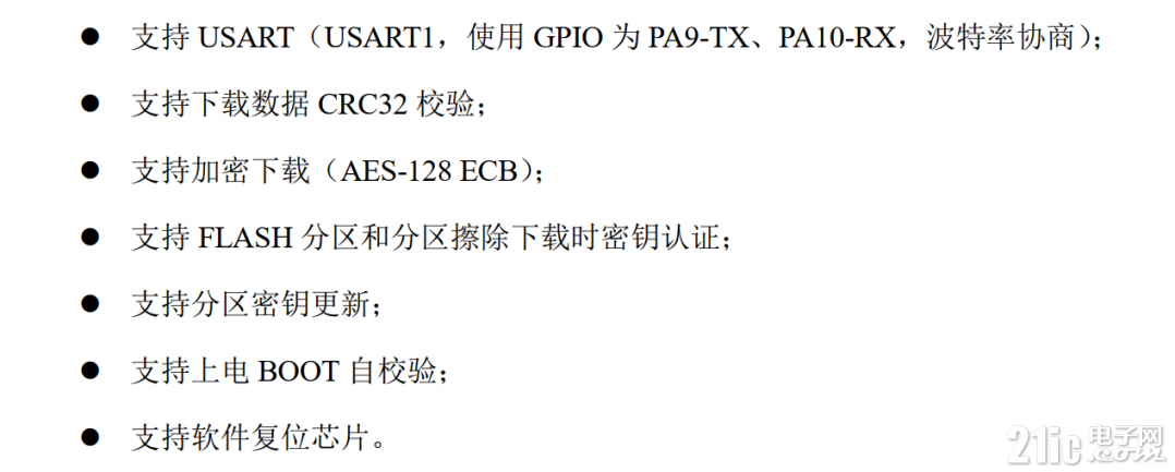
8.1 N32G430内置boot功能强大,具体支持功能如下:

8.2 N32G430 系列芯片的固件程序 BOOT,支持通过 USART 接口下载用户程序和数据。 相关命令格式如下:
上下层指令数据结构
1、上层指令结构:
<CMD_H + CMD_L + LEN + Par> + (DAT)。
CMD_H 代表一级命令字段, CMD_L 代表二级命令字段; LEN 代表发送数据长度; Par代表 4 个字节命令参数; DAT 代表上层指令往下层发送的具体数据;
2、下层应答结构:
< CMD_H + CMD_L + LEN > + (DAT) + <CR1+CR2>。
CMD_H 代表一级命令字段, CMD_L 代表二级命令字段,下层的命令字段和对应上层的命令字段相同; LEN 代表发送数据长度; DAT 代表下层向上层应答的具体数据; CR1+CR2代表向上层返回的指令执行结果,若上层发送命令一级、二级命令字段不属于任何命令, BOOT 回复 CR1=0xBB, CR2 = 0xCC。
串口支持的命令数据结构:
1、 上位机下发上层指令:
STA1 + STA2 + {上层指令结构} + XOR。
STA1 和 STA2 是串口发送命令的起始字节, STA1=0xAA, STA2=0x55。用于芯片识别上位机发送串口数据流。
XOR 代表之前命令字节的异或运算值(STA1 + STA2 + {上层指令结构})。
2、 上位机接收下层应答:
STA1 + STA2 + {下层应答结构} + XOR。
STA1 和 STA2 是串口发送命令的起始字节, STA1=0xAA, STA2=0x55。用于上位机识别芯片发送串口数据流
XOR 代表之前命令字节的异或运算值(STA1 + STA2 + {下层应答结构})。
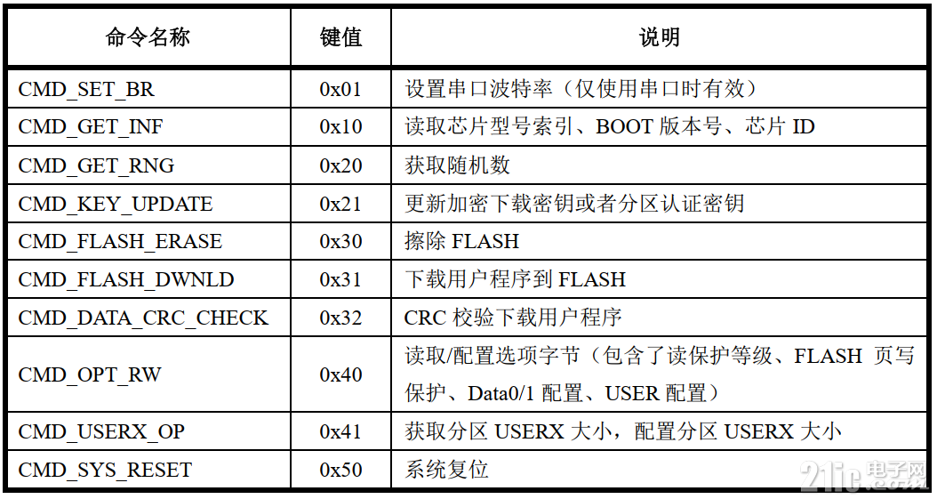
8.3 命令列表

8.4 命令说明和实例修改串口波特率

Par[0~3],串口波特率协商设置值可以设定最大,设定范围为 2.4Kbps ~ 4Mbps,默认波特率为 9600bps;
状态字节(CR1、 CR2)根据命令执行情况分为:
1. 返回成功:状态标志位(0xA0、 0x00)。
2. 返回失败:状态标志位(0xB0、 0x00)。