介绍
本博客适用于有一定单片机基础的学习爱好者。
Proteus仿真stm32第二集——数码管仿真
首先理解数码管的状态 7段数码管长包含7段发光二极管和一个小数点(其实也是一个发光二极管),要让数码管显示想要显示的值很简单,只需要让相应的发光二极管发光即可,这里还分共阳极和共阴极(本文选用共阳极),具体介绍参考博客:数码管介绍
懂了发光原理之后就很简单,如何让stm32芯片来配置相应的管脚值即可。
器件
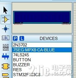
器件选择
打开Proteus,元器件模式选择stm32f103c8系列(103系列的都行,c等字母编号代表不同的管脚数量),其余参考下面的器件。74LS245是驱动增强型芯片,没有实际作用仿真可以不放(当然如果要做成实物是必须要的)

部分器件没用,只是之前其他仿真添加的不用管。
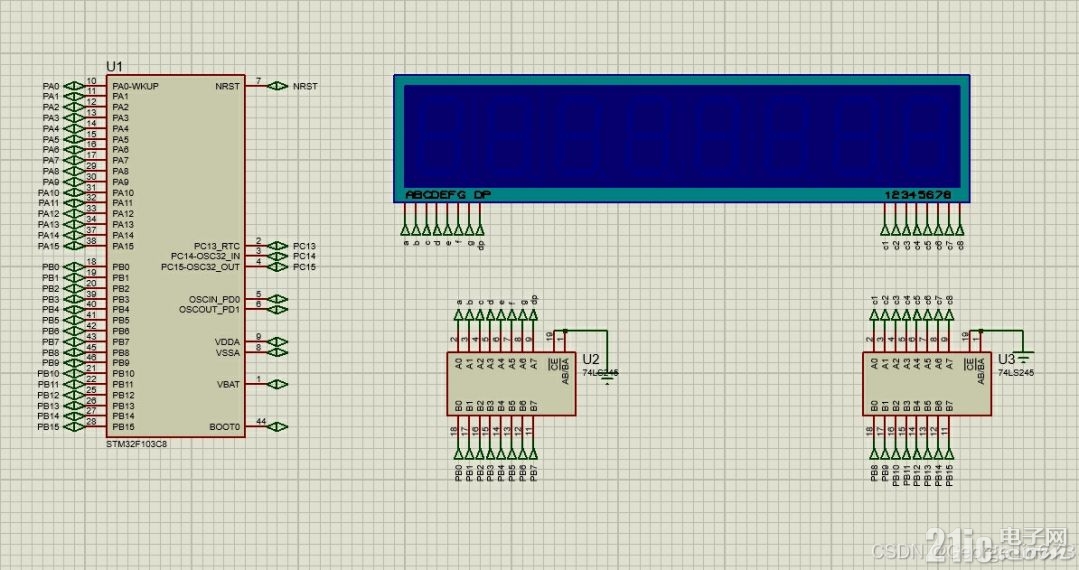
摆放器件 (如图所示)

引脚编辑,这个参考上一篇文章 (再提示一遍在左边栏的终端模式里!)
选择其中一个74LS245作为a到dp的驱动,另一个作为位选的驱动(这个很关键,为之后的动态数码管做铺垫),引脚分配参考上图,我们使用GPIOB口作为本次仿真端口,16个口够用了。
代码编写
首先配置GPIOB口,新建seg.c和seg.h在HAREWARE文件夹,编写如下
seg.h文件
#ifndef __SEG_H
#define __SEG_H
void Seg_Init(void);
void Seg_Tran(unsigned char *pucSeg_Char, unsigned short *pucSeg_Code);
void Seg_Disp(unsigned short *pucSeg_Code, unsigned char ucSeg_Pos);
#endif
这个说一下本来应该参照正常写法写 u8 或者 uint8_t, 但是它的typedef在一个叫stdint.h的头文件里,打开这个头文件,诶!不就是unsigned char吗,所以这里写u8 或者unsigned char都是可以的,作者的编译器这里写uint8_t老是给警告,为了不让它警告就写unsigned char了。

seg.c文件
#include "stm32f10x.h" // Device header
#include "seg.h"
void Seg_Init(void)
{
//声明一个结构体,名字是GPIO_InitStructure
GPIO_InitTypeDef GPIO_InitStructure;
//使能GPIOC的时钟,ENABLE代表使能
RCC_APB2PeriphClockCmd(RCC_APB2Periph_GPIOB,ENABLE);//GPIOB
GPIO_InitStructure.GPIO_Mode=GPIO_Mode_Out_PP;//推挽输出
GPIO_InitStructure.GPIO_Pin=GPIO_Pin_All; // 选中所有端口
GPIO_InitStructure.GPIO_Speed=GPIO_Speed_50MHz; // 最大反转速度
GPIO_Init(GPIOB,&GPIO_InitStructure); // 初始化
}
void Seg_Tran(uint8_t *pucSeg_Char, uint16_t *pucSeg_Code)
{
uint8_t i, j = 0;
uint16_t ucSeg_Code;
for(i = 0; i < 8; i++, j++)
{
switch(pucSeg_Char[j])
{
case '0': ucSeg_Code = 0x00c0; break; // dp g f e d c b a
case '1': ucSeg_Code = 0x00f9; break; // 1 1 1 1 1 0 0 1
case '2': ucSeg_Code = 0x00a4; break; // 1 0 1 0 0 1 0 0
case '3': ucSeg_Code = 0x00b0; break; // 1 0 1 1 0 0 0 0
case '4': ucSeg_Code = 0x0099; break; // 1 0 0 1 1 0 0 1
case '5': ucSeg_Code = 0x0092; break; // 1 0 0 1 0 0 1 0
case '6': ucSeg_Code = 0x0082; break; // 1 0 0 0 0 0 1 0
case '7': ucSeg_Code = 0x00f8; break; // 1 1 1 1 1 0 0 0
case '8': ucSeg_Code = 0x0080; break; // 1 0 0 0 0 0 0 0
case '9': ucSeg_Code = 0x0090; break; // 1 0 0 1 0 0 0 0
case 'A': ucSeg_Code = 0x0088; break; // 1 0 0 0 1 0 0 0
case 'B': ucSeg_Code = 0x0083; break; // 1 0 0 0 0 0 1 1
case 'C': ucSeg_Code = 0x00c6; break; // 1 1 0 0 0 1 1 0
case 'D': ucSeg_Code = 0x00A1; break; // 1 0 1 0 0 0 0 1
case 'E': ucSeg_Code = 0x0086; break; // 1 0 0 0 0 1 1 0
case 'F': ucSeg_Code = 0x008E; break; // 1 0 0 0 1 1 1 0
case 'H': ucSeg_Code = 0x0089; break; // 1 0 0 0 1 0 0 1
case 'L': ucSeg_Code = 0x00C7; break; // 1 1 0 0 0 1 1 1
case 'N': ucSeg_Code = 0x00C8; break; // 1 1 0 0 1 0 0 0
case 'P': ucSeg_Code = 0x008c; break; // 1 0 0 0 1 1 0 0
case 'U': ucSeg_Code = 0x00C1; break; // 1 1 0 0 0 0 0 1
case '-': ucSeg_Code = 0x00bf; break; // 1 0 1 1 1 1 1 1
default: ucSeg_Code = 0x00ff; // 1 1 1 1 1 1 1 1
}
if (pucSeg_Char[j+1] == '.')
{
ucSeg_Code &= 0x007f; // 点亮小数点
j++;
}
pucSeg_Code = ucSeg_Code;
}
}
void Seg_Disp(uint16_t *pucSeg_Code,uint8_t ucSeg_Pos)
{
uint16_t temp = 0x0100;
temp = temp << ucSeg_Pos;
GPIO_Write(GPIOB,pucSeg_Code[ucSeg_Pos] | temp);
}
这个得说明一下,初始化很简单,配置所有的GPIOB口为推挽输出的形式,最大反转频率50MHz,字符串转变函数:传入字符串的首字符指针和编码的首指针,字符都是常见的uint8_t足够,编码和51单片机同,GPIOB口一共有16位可用端口,因此需要使用uint16_t,具体编码如果有兴趣就自己算,不算复杂,略过。数码管显示函数:由于GPIOB 的 PB0 ~ PB7用来控制编码,因此使用PB8 ~ PB15来作为位选器。初始temp值 0x0100 = 0000 0001 0000 0000,相当于选中了PB8,通过传参来调整需要打开的数码管。
main.c文件
#include "stm32f10x.h"
#include "led.h" // led
#include "delay.h" // 延时
#include "key.h" // 按键
#include "seg.h" // 数码管
uint8_t pucSeg_Char[12] = {'0','1','2','3','4','5','6','7'}; // 显示字符
uint16_t pucSeg_Code[8]; // 显示代码
uint8_t ucSeg_Pos; // 显示位置
int main(void)
{
delay_init();
Seg_Init();
ucSeg_Pos = 0;
while(1){ //主循环
Seg_Tran(pucSeg_Char,pucSeg_Code);
Seg_Disp(pucSeg_Code,ucSeg_Pos);
if (++ucSeg_Pos == 8)
ucSeg_Pos = 0;
}
}
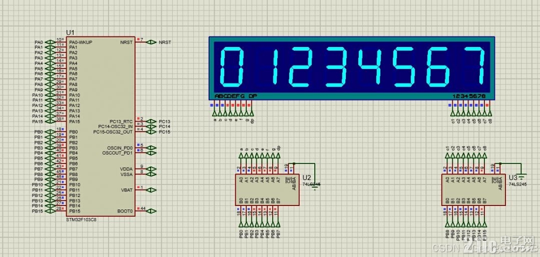
多余的头文件可要可不要,对于这个仿真没什么用。这里新增了一些变量来实现数码管的显示,更改字符串的值即可在数码管显示相应的内容。

静态数码管就是这样,如果需要动态数码管,简单的可以在主循环中添加延时函数,并适当更改字符串,复杂的则需要定时器的帮助以实现动态显示,这个有机会再分享吧。
————————————————
版权声明:本文为博主原创文章,遵循 CC 4.0 BY-SA 版权协议,转载请附上原文出处链接和本声明。
原文链接:https://blog.csdn.net/2302_80954675/article/details/142144688
|
|