使用模块如下图所示:
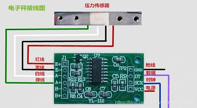
使用单片机为STM32C8T6,引脚DT -> PB7,SCK -> PB6,使用通道A
下面是驱动程序:
- void GPIO_Weigh_Init(void)
- {
- GPIO_InitTypeDef GPIO_InitStructure;
-
- RCC_APB2PeriphClockCmd(RCC_APB2Periph_GPIOB, ENABLE);
-
- GPIO_InitStructure.GPIO_Mode = GPIO_Mode_IN_FLOATING;
- GPIO_InitStructure.GPIO_Pin = GPIO_Pin_7;
- GPIO_Init(GPIOB, &GPIO_InitStructure);
-
- GPIO_InitStructure.GPIO_Mode = GPIO_Mode_Out_PP;
- GPIO_InitStructure.GPIO_Pin = GPIO_Pin_6;
- GPIO_InitStructure.GPIO_Speed = GPIO_Speed_50MHz;
- GPIO_Init(GPIOB, &GPIO_InitStructure);
- }
- uint32_t Read_Weigh(void)
- {
- uint8_t i;
- uint32_t value = 0;
-
- /**
- 数据手册写到,当数据输出管脚 DOUT 为高电平时,表明A/D 转换器还未准备好输出数据,此时串口时
- 钟输入信号 PD_SCK 应为低电平,所以下面设置引脚状态。
- **/
- GPIO_SetBits(GPIOB, GPIO_Pin_7); //初始状态DT引脚为高电平
- GPIO_ResetBits(GPIOB, GPIO_Pin_6); //初始状态SCK引脚为低电平
-
- /**
- 等待DT引脚变为高电平
- **/
- while(GPIO_ReadInputDataBit(GPIOB, GPIO_Pin_7));
- delay_us(1);
-
- /**
- 当 DOUT 从高电平变低电平后,PD_SCK 应输入 25 至 27 个不等的时钟脉冲
- 25个时钟脉冲 ---> 通道A 增益128
- 26个时钟脉冲 ---> 通道B 增益32
- 27个时钟脉冲 ---> 通道A 增益64
- **/
- for(i=0; i<24; i++) //24位输出数据从最高位至最低位逐位输出完成
- {
- // //方法一:
- // GPIO_SetBits(GPIOB, GPIO_Pin_6); //时钟高电平
- // value = value << 1; //如果DT位为低左移一位
- // delay_us(1);
- // GPIO_ResetBits(GPIOB, GPIO_Pin_6); //时钟低电平
- // if(GPIO_ReadInputDataBit(GPIOB, GPIO_Pin_7))
- // value++; //如果DT位为高,值+1
- // delay_us(1);
-
- //方法二:
- GPIO_SetBits(GPIOB, GPIO_Pin_6);
- delay_us(1);
- GPIO_ResetBits(GPIOB, GPIO_Pin_6);
- if(GPIO_ReadInputDataBit(GPIOB, GPIO_Pin_7) == 0)
- {
- value = value << 1;
- value |= 0x00;
- }
- if(GPIO_ReadInputDataBit(GPIOB, GPIO_Pin_7) == 1)
- {
- value = value << 1;
- value |= 0x01;
- }
- delay_us(1);
- }
-
- //第 25至 27 个时钟脉冲用来选择下一次 A/D 转换的输入通道和增益
- GPIO_SetBits(GPIOB, GPIO_Pin_6);
- value = value^0x800000;
- delay_us(1);
- GPIO_ResetBits(GPIOB, GPIO_Pin_6);
- delay_us(1);
- return value;
- }
| 


 楼主
楼主
