一、STM32U385RG低功耗
STM32U385xx Datasheet(stm32u385rg.pdf)关于低功耗的描述:
Low-power modes
The ultra-low-power STM32U385xx devices support several low-power modes to save power when the CPU does
not need to be kept running, for example when waiting for an external event. It is up to the user to select the mode
that gives the best compromise between low-power consumption, short startup time, and available wake-up
sources.
Table 8. STM32U385xx low-power modes overview details the related low-power modes.
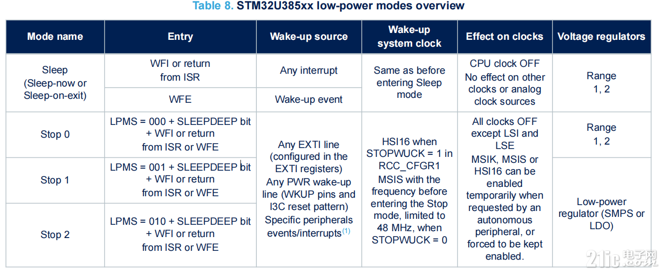
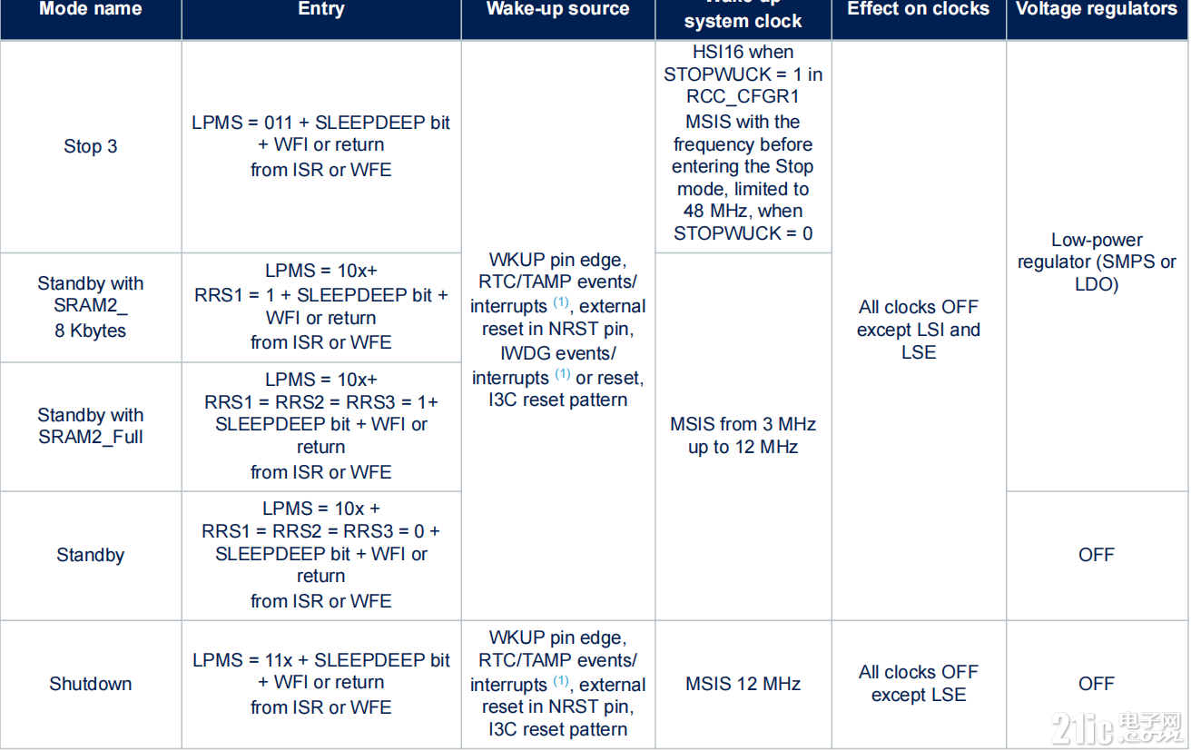
By default, the microcontroller is in Run mode after a system or a power reset. It is up to the user to select one of
the low-power modes described below:
•
Sleep mode
CPU clock off, all peripherals including Cortex®-M33 core such as NVIC and SysTick can run and wake up
the CPU when an interrupt or an event occurs.
•
Stop 0, Stop 1, Stop 2, and Stop 3 modes
Stop mode achieves the lowest power consumption while retaining the content of SRAM and registers. The
SRAMs can be totally or partially switched off to further reduce consumption. All clocks in the core domain
are stopped. The MSI (MSIS and MSIK) RC, the HSI16 RC and the HSE crystal oscillators are disabled.
The LSE or LSI is still running.
The RTC can remain active (Stop mode with RTC, Stop mode without RTC).
Some peripherals are autonomous and can operate in Stop mode by requesting their kernel clock and their
bus (APB or AHB) when needed, in order to transfer data with GPDMA1 depending on peripherals and
power mode.
In Stop 0 mode, the regulator remains in main regulator mode, allowing a very fast wake-up time but with
much higher consumption.
In Stop 1, the regulator is in low-power mode, and the whole core domain is fully powered. All autonomous
peripherals are functional.
In Stop 2 mode, most of the core domain (D1 domain) is put in a lower leakage mode, keeping registers
retention, but without any possible functionality. The D2 domain, embedding APB3 peripherals, is kept fully
powered, so those peripherals can be kept functional.
Stop 3 is the lowest power mode with full retention, but the functional peripherals and sources of wake-up
are reduced to the same ones than in Standby mode.
The system clock when exiting from Stop mode can be either MSIS up to 48 MHz or HSI16, depending on
software configuration.
Standby mode
The Standby mode is used to achieve the lowest power consumption with BOR. The internal regulator is
switched off so that the core domain is powered off. The MSI (MSIS and MSIK) RC, the HSI16 RC and the
HSE crystal oscillators are also switched off.
The RTC can remain active (Standby mode with RTC, Standby mode without RTC).
The brownout reset (BOR) always remains active in Standby mode.
The state of each I/O during Standby mode can be selected by software: I/O with internal pull-up, internal
pull-down or floating.
After entering Standby mode, SRAMs and register contents are lost except for registers in the backup
domain and Standby circuitry. Optionally, the full SRAM2 or 8 Kbytes or 24 Kbytes or 32 Kbytes can be
retained in Standby mode, supplied by the low-power regulator (standby with SRAM2 retention mode).
The BOR can be configured in ultra-low-power mode to further reduce power consumption during Standby
mode.
The device exits Standby mode when an external reset (NRST pin), an IWDG early wake-up event or
reset, WKUP pin event (configurable rising or falling edge), an RTC event (alarm, periodic wake-up,
timestamp), a tamper detection, or a I3C reset pattern detection occurs.
The system clock after wake-up is MSIS up to 12 MHz.
•
Shutdown mode
The Shutdown mode allows the lowest power consumption. The internal regulator is switched off so that
the core domain is powered off. The HSI16, the MSI (MSIS and MSIK), the LSI, and the HSE oscillators are
also switched off.
The RTC can remain active (Shutdown mode with RTC, Shutdown mode without RTC).
The BOR is not available in Shutdown mode. No power voltage monitoring is possible in this mode,
therefore the switch to backup domain is not supported.
SRAMs and register contents are lost except for registers in the backup domain.
The device exits Shutdown mode when an external reset (NRST pin), a WKUP pin event (configurable
rising or falling edge), or an RTC event occurs (alarm, periodic wake-up, timestamp), a tamper detection or
a I3C reset pattern detection.
The system clock after wake-up is MSIS at 12 MHz.
二、低功耗模式测试
从数据手册上看,STM32U385RG提供了很多种低功耗模式,为了简化测试,不考虑细节,可以归纳为:sleep、Stop、Standby、Shutdown等基
本模式。
1、通过USART1选择低功耗模式
main函数增加:
- MX_USART1_UART_Init();
- /* USER CODE BEGIN 2 */
- HAL_Delay(5000);
- // 初始提示信息
- const char *menu = "\r\nSelect Low Power Mode:\r\n"
- "1. Sleep Mode\r\n"
- "2. Stop Mode\r\n"
- "3. Standby Mode\r\n"
- "4. Shutdown Mode\r\n"
- "Enter choice (1-4): ";
- HAL_UART_Transmit(&huart1, (uint8_t*)menu, strlen(menu), HAL_MAX_DELAY);
-
- // 启动UART接收
- HAL_UART_Receive_IT(&huart1, uart_rx_buffer, 1);
USART1初始化
MX_USART1_UART_Init();
HAL_Delay(5000);//延时5秒
HAL_UART_Receive_IT(&huart1, uart_rx_buffer, 1);//使能接收中断
接收中断函数
- void HAL_UART_RxCpltCallback(UART_HandleTypeDef *huart)
- {
- static uint8_t index = 0;
-
- if (huart->Instance == USART1)
- {
- if (uart_rx_buffer[0] == '\r' || uart_rx_buffer[0] == '\n')
- {
- input_command[index] = '\0';
- cmd_received = 1;
- index = 0;
- }
- else
- {
- input_command[index++] = uart_rx_buffer[0];
- if (index >= sizeof(input_command)-1) index = 0;
- }
-
- // 重新启动接收
- HAL_UART_Receive_IT(huart, uart_rx_buffer, 1);
- }
- }
main函数while(1)处理
- while (1)
- {
- if (cmd_received)
- {
- cmd_received = 0;
- ProcessCommand(input_command);
- memset(input_command, 0, sizeof(input_command));
- }
-
- // 低功耗处理
- if (uart_rx_flag == 0)
- {
- __HAL_PWR_CLEAR_FLAG(PWR_WAKEUP_FLAG2);
- HAL_SuspendTick(); // 关闭SysTick中断
- HAL_NVIC_DisableIRQ(EXTI13_IRQn); // 关闭GPIO中断
- HAL_PWR_EnterSLEEPMode(PWR_MAINREGULATOR_ON, PWR_SLEEPENTRY_WFI);
- HAL_ResumeTick();
- HAL_NVIC_EnableIRQ(EXTI13_IRQn);
- }
-
- /* USER CODE END WHILE */
- /* USER CODE BEGIN 3 */
- }
如果uart_rx_flag=0,进入sleep模式
2、根据输入进入低功耗模式
1:Sleep
2:Stop
3:Standby
4:Shutdown
- void ProcessCommand(char *cmd)
- {
- if(uart_rx_flag==0) return;
-
- if (strcmp(cmd, "1") == 0)
- {
- HAL_UART_Transmit(&huart1, (uint8_t*)"\r\nEntering Sleep Mode...\r\n", 26, HAL_MAX_DELAY);
- uart_rx_flag = 0; // 允许进入低功耗
- return;
- }
- else if (strcmp(cmd, "2") == 0)
- {
- HAL_UART_Transmit(&huart1, (uint8_t*)"\r\nEntering Stop Mode...\r\n", 25, HAL_MAX_DELAY);
- HAL_UART_Transmit(&huart1, (uint8_t*)"Press USER button to wake up\r\n", 30, HAL_MAX_DELAY);
-
-
- HAL_PWR_DisableWakeUpLine(PWR_WAKEUP_LINE2);
- __HAL_PWR_CLEAR_FLAG(PWR_WAKEUP_FLAG2);
- HAL_PWR_EnableWakeUpLine(PWR_WAKEUP_LINE2, PWR_WAKEUP_SELECT_1, PWR_WAKEUP_POLARITY_HIGH);
-
- // 进入Stop模式
- HAL_PWR_EnterSTOPMode(PWR_LOWPOWERREGULATOR_ON, PWR_STOPENTRY_WFI);
-
- // 唤醒后重新初始化
- SystemClock_Config();
- MX_USART1_UART_Init();
- HAL_UART_Transmit(&huart1, (uint8_t*)"Woke up from Stop Mode\r\n", 24, HAL_MAX_DELAY);
- }
- else if (strcmp(cmd, "3") == 0)
- {
- HAL_UART_Transmit(&huart1, (uint8_t*)"\r\nEntering Standby Mode...\r\n", 28, HAL_MAX_DELAY);
- HAL_UART_Transmit(&huart1, (uint8_t*)"Press USER button to wake up\r\n", 30, HAL_MAX_DELAY);
-
- HAL_PWR_DisableWakeUpLine(PWR_WAKEUP_LINE2);
- __HAL_PWR_CLEAR_FLAG(PWR_WAKEUP_FLAG2);
- HAL_PWR_EnableWakeUpLine(PWR_WAKEUP_LINE2, PWR_WAKEUP_SELECT_1, PWR_WAKEUP_POLARITY_HIGH);
-
- // 进入Standby模式
- HAL_PWR_EnterSTANDBYMode();
-
- // 唤醒后会从复位开始执行,不会到达这里
- }
- else if (strcmp(cmd, "4") == 0)
- {
- HAL_UART_Transmit(&huart1, (uint8_t*)"\r\nEntering Shutdown Mode...\r\n", 29, HAL_MAX_DELAY);
- HAL_UART_Transmit(&huart1, (uint8_t*)"Press USER button to wake up\r\n", 30, HAL_MAX_DELAY);
-
- HAL_PWR_DisableWakeUpLine(PWR_WAKEUP_LINE2);
- __HAL_PWR_CLEAR_FLAG(PWR_WAKEUP_FLAG2);
- HAL_PWR_EnableWakeUpLine(PWR_WAKEUP_LINE2, PWR_WAKEUP_SELECT_1, PWR_WAKEUP_POLARITY_HIGH);
-
- // 关闭所有可能影响唤醒的外设
- HAL_UART_DeInit(&huart1);
-
- // 进入Shutdown模式
- HAL_PWREx_EnterSHUTDOWNMode();
-
- // 唤醒后会从复位开始执行(不会执行到这里)
- }
- else
- {
- HAL_UART_Transmit(&huart1, (uint8_t*)"\r\nInvalid choice!\r\n", 19, HAL_MAX_DELAY);
- }
-
- // 重新显示菜单
- const char *menu = "\r\nSelect Low Power Mode:\r\n"
- "1. Sleep Mode\r\n"
- "2. Stop Mode\r\n"
- "3. Standby Mode\r\n"
- "4. Shutdown Mode\r\n"
- "Enter choice (1-4): ";
- HAL_UART_Transmit(&huart1, (uint8_t*)menu, strlen(menu), HAL_MAX_DELAY);
- }
三、测量
万用表调到电流档,从JP4串联接入

根据USART输入进入低功耗模式,Stop、Standby、Shutdown可以通过PC13唤醒

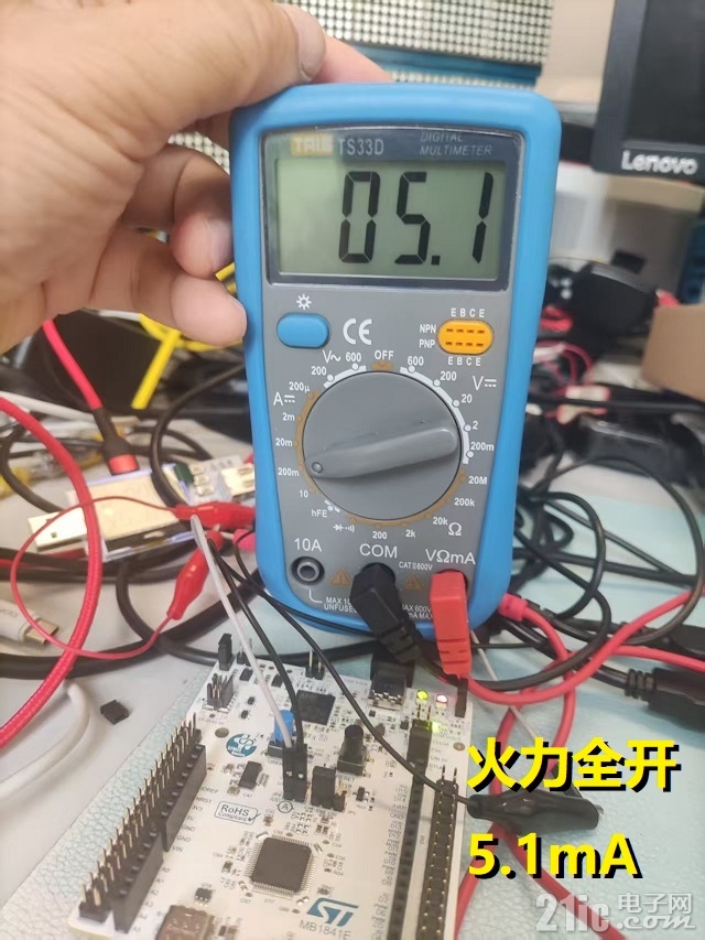
1、运行Toggle_Led&USART1时功耗:
模式:正常运行,电流:5.1mA,功耗:3.3*5.1=16.83mw
2、Sleep模式

模式:Sleep,电流:0.9mA,功耗:3.3*0.9=2.97mw
3、Stop模式

模式:Stop,电流:123.6uA,功耗:3.3*0.1236=0.40788mw
4、Standby模式
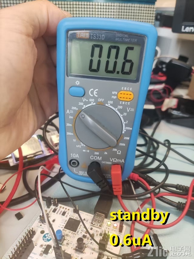
模式:Standby,电流:0.6uA,功耗:3.3*0.6=1.98uw
5、Shutdown模式
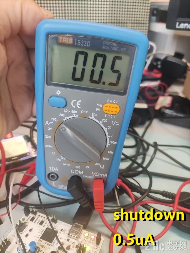
模式:Shutdown,电流:0.5uA,功耗:3.3*0.5=1.65uw
|