- void i2c_lowlevel_init(i2c_handle_type* hi2c)
- {
- gpio_init_type gpio_init_structure;
- if(hi2c->i2cx == I2Cx_PORT)
- {
- crm_periph_clock_enable(I2Cx_CLK, TRUE);
- crm_periph_clock_enable(I2Cx_SCL_GPIO_CLK, TRUE);
- crm_periph_clock_enable(I2Cx_SDA_GPIO_CLK, TRUE);
- gpio_pin_mux_config(I2Cx_SCL_GPIO_PORT, I2Cx_SCL_GPIO_PinsSource, I2Cx_SCL_GPIO_MUX);
- gpio_pin_mux_config(I2Cx_SDA_GPIO_PORT, I2Cx_SDA_GPIO_PinsSource, I2Cx_SDA_GPIO_MUX);
- gpio_init_structure.gpio_drive_strength = GPIO_DRIVE_STRENGTH_STRONGER;
- gpio_init_structure.gpio_mode = GPIO_MODE_MUX;
- gpio_init_structure.gpio_out_type = GPIO_OUTPUT_OPEN_DRAIN;
- gpio_init_structure.gpio_pull = GPIO_PULL_UP;
- gpio_init_structure.gpio_pins = I2Cx_SCL_GPIO_PIN;
- gpio_init(I2Cx_SCL_GPIO_PORT, &gpio_init_structure);
- gpio_init_structure.gpio_pins = I2Cx_SDA_GPIO_PIN;
- gpio_init(I2Cx_SDA_GPIO_PORT, &gpio_init_structure);
- i2c_init(hi2c->i2cx, 0x0F, I2Cx_CLKCTRL);
- i2c_own_address1_set(hi2c->i2cx, I2C_ADDRESS_MODE_7BIT, I2Cx_ADDRESS);
- }
- }
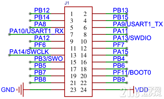
OLED屏所使用的接口为J1,见图1所示。

图1 所用接口
相较于软件方式,硬件方式省去了字节数据发送函数及相关辅助函数的构建。
此时,只需调用函数 i2c_master_transmit()即可构建相应的指令发送函数和数据发送函数,其内容如下:
- void Write_IIC_Command(unsigned char IIC_Command)
- {
- unsigned char Data[2]={0x00,0x00};
- Data[1]=IIC_Command;
- hi2cx.i2cx = I2C1;
- i2c_master_transmit(&hi2cx, 0x78, Data, 2, I2C_TIMEOUT);
- }
- void Write_IIC_Data(unsigned char IIC_Data)
- {
- unsigned char Data[2]={0x40,0x00};
- Data[1]=IIC_Data;
- hi2cx.i2cx = I2C1;
- i2c_master_transmit(&hi2cx, 0x78, Data, 2, I2C_TIMEOUT);
- }
- void OLED_WR_Byte(unsigned dat,unsigned cmd)
- {
- if(cmd)
- {
- Write_IIC_Data(dat);
- }
- else
- {
- Write_IIC_Command(dat);
- }
- }
在此基础上,就可以直接与OLED的功能函数实现对接。
对于单色的OLED屏来说其参数化函数为:
- void OLED_0_96D_Init(void)
- {
- OLED_WR_Byte(0xAE,OLED_CMD);
- OLED_WR_Byte(0x00,OLED_CMD);
- OLED_WR_Byte(0x10,OLED_CMD);
- OLED_WR_Byte(0x40,OLED_CMD);
- OLED_WR_Byte(0x81,OLED_CMD);
- OLED_WR_Byte(0xCF,OLED_CMD);
- OLED_WR_Byte(0xA1,OLED_CMD);
- OLED_WR_Byte(0xC8,OLED_CMD);
- OLED_WR_Byte(0xA6,OLED_CMD);
- OLED_WR_Byte(0xA8,OLED_CMD);
- OLED_WR_Byte(0x3f,OLED_CMD);
- OLED_WR_Byte(0xD3,OLED_CMD);
- OLED_WR_Byte(0x00,OLED_CMD);
- OLED_WR_Byte(0xd5,OLED_CMD);
- OLED_WR_Byte(0x80,OLED_CMD);
- OLED_WR_Byte(0xD9,OLED_CMD);
- OLED_WR_Byte(0xF1,OLED_CMD);
- OLED_WR_Byte(0xDA,OLED_CMD);
- OLED_WR_Byte(0x12,OLED_CMD);
- OLED_WR_Byte(0xDB,OLED_CMD);
- OLED_WR_Byte(0x40,OLED_CMD);
- OLED_WR_Byte(0x20,OLED_CMD);
- OLED_WR_Byte(0x02,OLED_CMD);
- OLED_WR_Byte(0x8D,OLED_CMD);
- OLED_WR_Byte(0x14,OLED_CMD);
- OLED_WR_Byte(0xA4,OLED_CMD);
- OLED_WR_Byte(0xA6,OLED_CMD);
- OLED_Clear();
- OLED_WR_Byte(0xAF,OLED_CMD);
- }
测试OLED屏的主程序为:
- int main(void)
- {
- i2c_status_type i2c_status;
- system_clock_config();
- hi2cx.i2cx = I2Cx_PORT;
- i2c_config(&hi2cx);
- OLED_0_96D_Init();
- OLED_ShowString(8,0,"AT32m412",16);
- OLED_ShowString(8,3, "0.96' OLED!",16);
- while(1);
- }
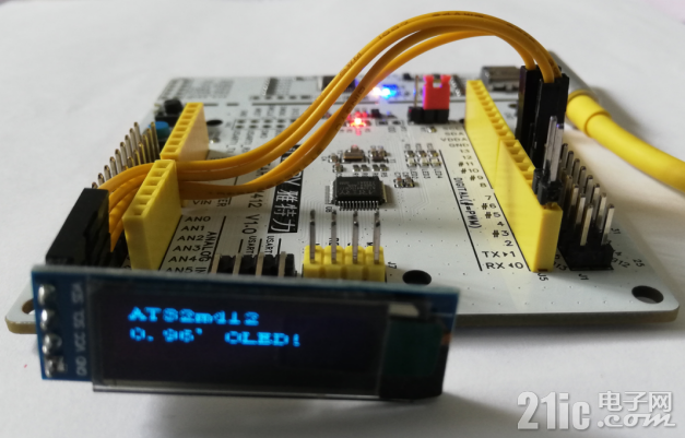
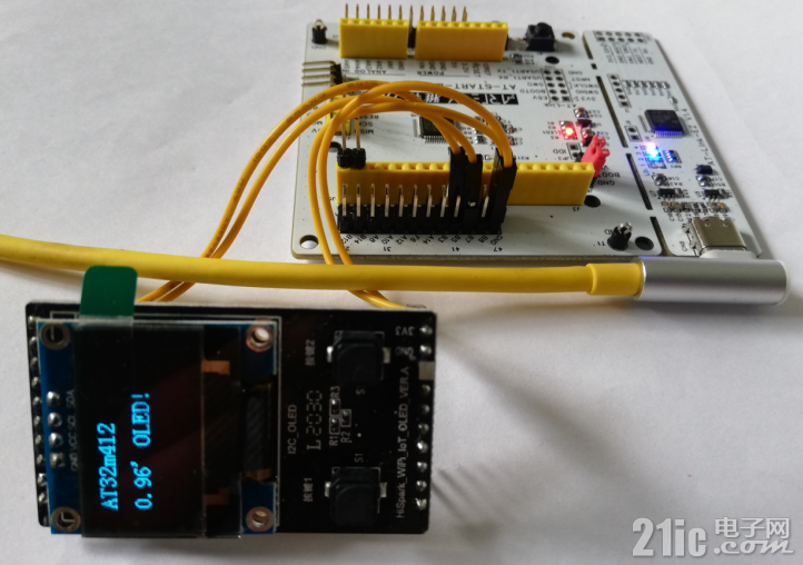
经程序的编译和下载,其测试效果如图2所示。

图2 0.91寸屏显示效果

图3 0.96寸屏显示效果