- void ADC_Function_Init(void)
- {
- ADC_InitTypeDef ADC_InitStructure={0};
- GPIO_InitTypeDef GPIO_InitStructure={0};
- //开启时钟
- RCC_APB2PeriphClockCmd(RCC_APB2Periph_GPIOA , ENABLE );
- RCC_APB2PeriphClockCmd(RCC_APB2Periph_ADC1 , ENABLE );
- RCC_APB2PeriphClockCmd(RCC_APB2Periph_ADC2 , ENABLE );
- RCC_ADCCLKConfig(RCC_PCLK2_Div8);
- //配置引脚
- GPIO_InitStructure.GPIO_Pin = GPIO_Pin_0 |GPIO_Pin_1 | GPIO_Pin_2 |GPIO_Pin_3;
- GPIO_InitStructure.GPIO_Mode = GPIO_Mode_AIN;
- GPIO_Init(GPIOA, &GPIO_InitStructure);
- ADC_DeInit(ADC1);
- ADC_DeInit(ADC2);
- //配置ADC参数
- ADC_InitStructure.ADC_Mode = ADC_Mode_RegSimult;
- ADC_InitStructure.ADC_ScanConvMode = ENABLE;
- ADC_InitStructure.ADC_ContinuousConvMode = DISABLE;
- ADC_InitStructure.ADC_ExternalTrigConv = ADC_ExternalTrigConv_None;
- ADC_InitStructure.ADC_DataAlign = ADC_DataAlign_Right;
- ADC_InitStructure.ADC_NbrOfChannel = 2;
- ADC_InitStructure.ADC_OutputBuffer = ADC_OutputBuffer_Disable;
- ADC_InitStructure.ADC_Pga = ADC_Pga_1;
- ADC_Init(ADC1, &ADC_InitStructure);
- //ADC规则通道配置
- ADC_RegularChannelConfig(ADC1, ADC_Channel_0, 1, ADC_SampleTime_239Cycles5 );
- ADC_RegularChannelConfig(ADC1, ADC_Channel_1, 2, ADC_SampleTime_239Cycles5 );
- ADC_DMACmd(ADC1, ENABLE);
- ADC_Cmd(ADC1, ENABLE);
- ADC_BufferCmd(ADC1, DISABLE); //disable buffer
- //开启校准
- ADC_ResetCalibration(ADC1);
- while(ADC_GetResetCalibrationStatus(ADC1));
- ADC_StartCalibration(ADC1);
- while(ADC_GetCalibrationStatus(ADC1));
- Calibrattion_Val1 = Get_CalibrationValue(ADC1);
- ADC_Init(ADC2, &ADC_InitStructure);
- ADC_RegularChannelConfig(ADC2, ADC_Channel_2, 1, ADC_SampleTime_239Cycles5 );
- ADC_RegularChannelConfig(ADC2, ADC_Channel_3, 2, ADC_SampleTime_239Cycles5 );
- ADC_SoftwareStartConvCmd(ADC2, ENABLE);
- ADC_Cmd(ADC2, ENABLE);
- ADC_BufferCmd(ADC2, DISABLE); //disable buffer
- ADC_ResetCalibration(ADC2);
- while(ADC_GetResetCalibrationStatus(ADC2));
- ADC_StartCalibration(ADC2);
- while(ADC_GetCalibrationStatus(ADC2));
- Calibrattion_Val2 = Get_CalibrationValue(ADC2);
-
- }
- void DMA_Tx_Init( DMA_Channel_TypeDef* DMA_CHx, u32 ppadr, u32 memadr, u16 bufsize)
- {
- DMA_InitTypeDef DMA_InitStructure={0};
- NVIC_InitTypeDef NVIC_InitStructure={0};
- RCC_AHBPeriphClockCmd( RCC_AHBPeriph_DMA1, ENABLE );
- DMA_DeInit(DMA_CHx);
- DMA_InitStructure.DMA_PeripheralBaseAddr = ppadr;
- DMA_InitStructure.DMA_MemoryBaseAddr = memadr;
- DMA_InitStructure.DMA_DIR = DMA_DIR_PeripheralSRC;
- DMA_InitStructure.DMA_BufferSize = bufsize;
- DMA_InitStructure.DMA_PeripheralInc = DMA_PeripheralInc_Disable;
- DMA_InitStructure.DMA_MemoryInc = DMA_MemoryInc_Enable;
- DMA_InitStructure.DMA_PeripheralDataSize = DMA_PeripheralDataSize_Word;
- DMA_InitStructure.DMA_MemoryDataSize = DMA_MemoryDataSize_Word;
- DMA_InitStructure.DMA_Mode = DMA_Mode_Circular;
- DMA_InitStructure.DMA_Priority = DMA_Priority_VeryHigh;
- DMA_InitStructure.DMA_M2M = DMA_M2M_Disable;
- DMA_Init( DMA_CHx, &DMA_InitStructure );
- NVIC_InitStructure.NVIC_IRQChannel = DMA1_Channel1_IRQn;
- NVIC_InitStructure.NVIC_IRQChannelPreemptionPriority = 2;
- NVIC_InitStructure.NVIC_IRQChannelSubPriority = 0;
- NVIC_InitStructure.NVIC_IRQChannelCmd = ENABLE;
- NVIC_Init(&NVIC_InitStructure);
- DMA_ITConfig( DMA1_Channel1, DMA_IT_TC | DMA_IT_HT | DMA_IT_TE, ENABLE );
- }
- //中断函数声明
- void DMA1_Channel1_IRQHandler(void) __attribute__((interrupt("WCH-Interrupt-fast")));
- void DMA1_Channel1_IRQHandler()
- {
- if(DMA_GetITStatus(DMA1_IT_TC1)==SET )
- {
- DMA_ClearITPendingBit(DMA1_IT_GL1);
- Adc_Val[0]=TxBuf[0]&0xffff;//PA0
- Adc_Val[1]=(TxBuf[0]>>16)&0xffff;//PA2
- Adc_Val[2]=TxBuf[1]&0xffff;//PA1
- Adc_Val[3]=(TxBuf[1]>>16)&0xffff;//PA3
- }
- }
6、实测数据
1)串口输出
2)根据串口的输出数据绘制曲线
四个通道的数据如下
可以看到通道0和1的波动比较大,在40mV左右,通道2和3的波动不大,在6mV左右。
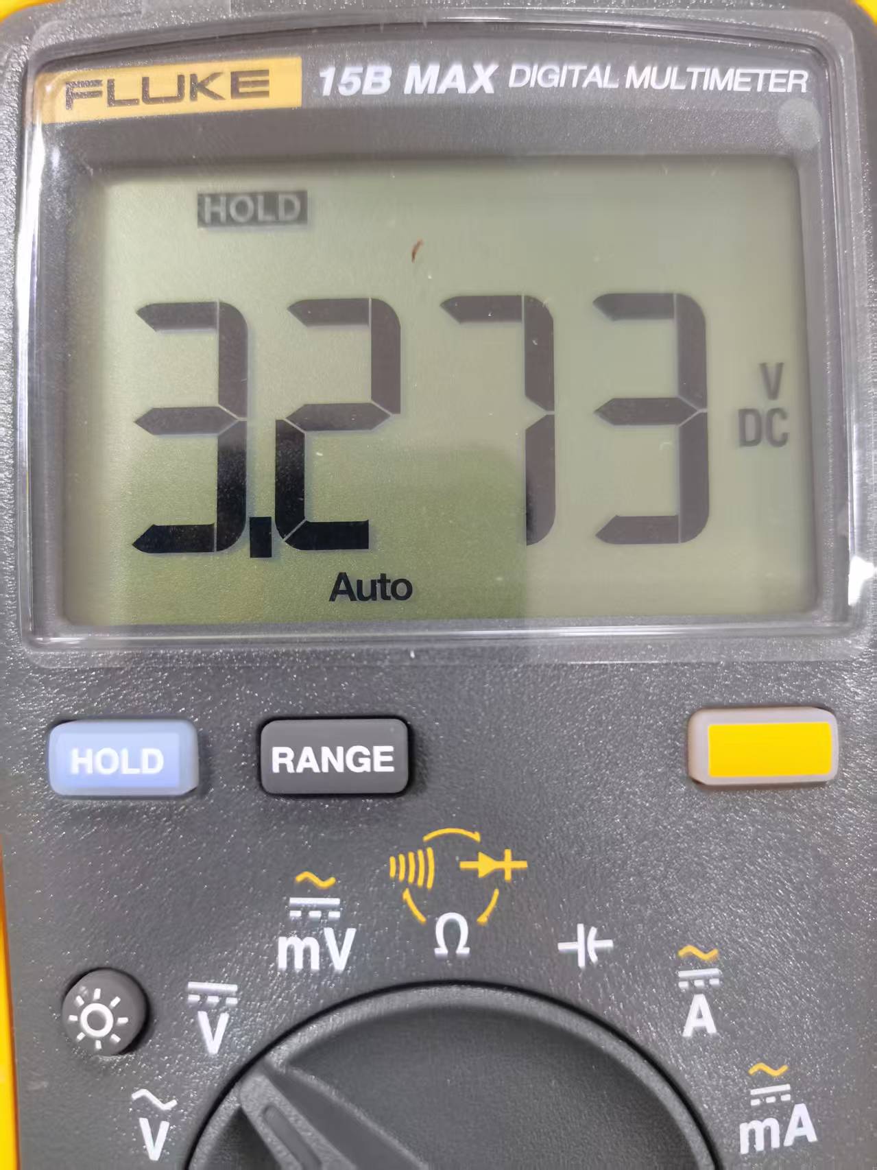
3)使用万一万用表测量,4个被测点的电压,基本都在3.274V,与ADC实测值,相差20mV,误差接近0.7%.还算比较准吧

综上,CH32V307 ADC用于对于精度不高的场合,还是绰绰有余的。